Lexus RX (RX 350L, RX450h) 2016-2026 Repair Manual: Removal
REMOVAL
CAUTION / NOTICE / HINT
The necessary procedures (adjustment, calibration, initialization, or registration) that must be performed after parts are removed and installed, or replaced during ultrasonic sensor removal/installation are shown below.
Necessary Procedures After Parts Removed/Installed/Replaced| Replaced Part or Performed Procedure | Necessary Procedure | Effect/Inoperative Function when Necessary Procedure not Performed | Link |
|---|---|---|---|
|
*1: When performing learning using the Techstream.
Click here | |||
| Disconnect cable from negative battery terminal | Memorize steering angle neutral point | Lane Control System | |
| Pre-collision System | |||
| Intelligent Clearance Sonar System*1 | |||
| Parking Assist Monitor System | | ||
| Panoramic View Monitor System | | ||
| Lighting System (w/ Automatic Headlight Beam Level Control System) | | ||
| Initialize back door lock | Power Door Lock Control System | | |
| Reset back door close position | Power Back Door System (w/ Outside Door Control Switch) | | |
| Rear bumper assembly or ultrasonic sensor |
|
| |
PROCEDURE
1. REMOVE REAR BUMPER ASSEMBLY (w/o Rear No. 2 Seat)
Click here .gif)
2. REMOVE REAR BUMPER ASSEMBLY (w/ Rear No. 2 Seat)
Click here
3. REMOVE REAR CENTER ULTRASONIC SENSOR
HINT:
The illustration is for the LH side. Use the same procedure for the RH side and LH side.
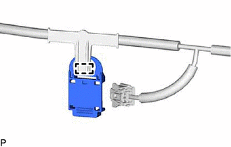
(a) Disconnect the connector.
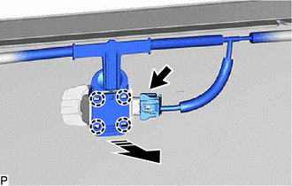
.png) | Remove in this Direction |
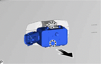
(b) Disengage the 4 claws as shown in the illustration.
(c) Disengage the 2 claws and remove the rear center ultrasonic sensor as shown in the illustration.
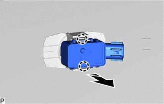
| | Remove in this Direction |
4. REMOVE REAR CORNER ULTRASONIC SENSOR
HINT:
The illustration is for the LH side. The orientation for the RH side is the opposite of the LH side.
(a) for RH Side with Rear No. 2 Seat:
(1) Disconnect the connector.
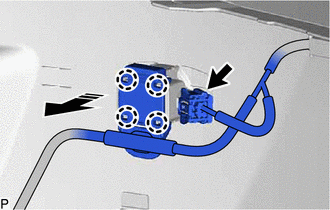
| | Remove in this Direction |
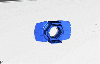
(2) Disengage the 4 claws as shown in the illustration.
(b) except RH Side with Rear No. 2 Seat:
| (1) Disconnect the connector. |
|
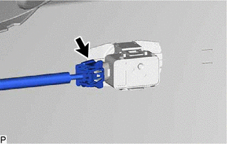
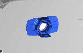
(c) Disengage the 2 claws and remove the rear corner ultrasonic sensor as shown in the illustration.
| | Remove in this Direction |
5. REMOVE ULTRASONIC SENSOR CLIP
HINT:
- Perform this procedure only when replacement of the ultrasonic sensor clip is necessary.
- Use the same procedure for all ultrasonic sensor clips.
| (a) Disengage the clamp to remove the ultrasonic sensor clip from the wire. |
|
6. REMOVE REAR CENTER ULTRASONIC SENSOR RETAINER
HINT:
- Perform this procedure only when replacement of the rear center ultrasonic sensor retainer is necessary.
- When removing the rear center ultrasonic sensor retainer, heat the rear bumper assembly and rear center ultrasonic sensor retainer using a heat light.
- The illustration is for the LH side. Use the same procedure for the RH side and LH side.
(a) Heat the rear bumper assembly and rear center ultrasonic sensor retainer using a heat light at the specified temperature for 3 to 5 minutes.
Heating Temperature:
| Item | Temperature |
|---|---|
| Rear Bumper Assembly | 40 to 60°C (104 to 140°F) |
| Rear Center Ultrasonic Sensor Retainer |
CAUTION:
- Do not touch the heat light and heated parts.
- Touching the heat light may result in burns.
- Touching heated parts for a long time may result in burns.
.png)
| *a | Heated Part |
| *b | Heat Light |
| (b) Remove the rear center ultrasonic sensor retainer. |
|
7. REMOVE REAR CORNER ULTRASONIC SENSOR RETAINER
HINT:
- Perform this procedure only when replacement of the rear corner ultrasonic sensor retainer is necessary.
- When removing the rear corner ultrasonic sensor retainer, heat the rear bumper assembly and rear corner ultrasonic sensor retainer using a heat light.
- The illustration is for the LH side. Use the same procedure for the RH side and LH side.
(a) Heat the rear bumper assembly and rear corner ultrasonic sensor retainer using a heat light at the specified temperature for 3 to 5 minutes.
Heating Temperature:
| Item | Temperature |
|---|---|
| Rear Bumper Assembly | 40 to 60°C (104 to 140°F) |
| Rear Corner Ultrasonic Sensor Retainer |
CAUTION:
- Do not touch the heat light and heated parts.
- Touching the heat light may result in burns.
- Touching heated parts for a long time may result in burns.
| *a | Heated Part |
| *b | Heat Light |
| (b) Remove the rear corner ultrasonic sensor retainer. |
|
 Inspection
INSPECTION PROCEDURE 1. INSPECT REAR CENTER ULTRASONIC SENSOR (a) Measure the resistance according to the value(s) in the table below. Standard Resistance: Tester Connection Condition Speci ...
 Installation
INSTALLATION PROCEDURE 1. INSTALL REAR CORNER ULTRASONIC SENSOR RETAINER HINT:
Perform this procedure only when replacement of the rear corner ultrasonic sensor retainer is necessary.
If a rear c ...
Other materials:
Lexus RX (RX 350L, RX450h) 2016-2026 Repair Manual > Navigation System: Speaker Circuit
DESCRIPTION If there is a short in a speaker circuit, the stereo component amplifier assembly detects it and stops output to the speakers. Thus sound cannot be heard from the speakers even if there is no malfunction in the stereo component amplifier assembly, DCM (telematics transceiver) or speakers ...
Lexus RX (RX 350L, RX450h) 2016-2026 Owners Manual > Driving procedures: Power (ignition) switch
Performing the following operations when carrying the electronic key on
your
person starts the hybrid system or changes power switch modes.
Starting the hybrid system
1. Check that the parking brake is set.
2. Check that the shift lever is in P.
3. Firmly depress the brake pedal.
and a
...
Lexus RX (RX 350L, RX450h) 2016-{YEAR} Owners Manual
- For your information
- Pictorial index
- For safety and security
- Instrument cluster
- Operation of each component
- Driving
- Lexus Display Audio system
- Interior features
- Maintenance and care
- When trouble arises
- Vehicle specifications
- For owners
Lexus RX (RX 350L, RX450h) 2016-{YEAR} Repair Manual

0.0085