Lexus RX (RX 350L, RX450h) 2016-2026 Repair Manual: Terminals Of Ecu
TERMINALS OF ECU
HINT:
Check from the rear of the connector while it is connected to the components.
DCM (TELEMATICS TRANSCEIVER)
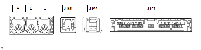
| Terminal No. (Symbol) | Wiring Color | Terminal Description | Condition | Specified Condition |
|---|---|---|---|---|
| J157-1 (+B) - J157-20 (E) | Y - W-B | Power source (+B) | Always | 11 to 14 V |
| J157-20 (E) - Body ground | W-B - Body ground | Ground | Always | Below 1 Ω |
| J157-19 (IG2) - J157-20 (E) | B - W-B | Power source (IG) | Engine switch on (IG) | 11 to 14 V |
| Engine switch off | Below 1 V | |||
| J157-25 (CANP) | R | CAN communication signal | - | - |
| J157-26 (CANN) | W | CAN communication signal | - | - |
| J157-30 (SLPD) - J157-20 (E) | B - W-B | Steering lock bar position signal | Steering locked | 11 to 14 V |
| Steering unlocked | Below 1.5 V |
CERTIFICATION ECU (SMART KEY ECU ASSEMBLY)
Click here .gif)
 Problem Symptoms Table
PROBLEM SYMPTOMS TABLE HINT:
Use the table below to help determine the cause of problem symptoms. If multiple suspected areas are listed, the potential causes of the symptoms are listed in order of ...
 Dtc Check / Clear
DTC CHECK / CLEAR CHECK DTC (a) Connect the Techstream to the DLC3. (b) Turn the engine switch on (IG). (c) Turn the Techstream on. (d) Enter the following menus: Body Electrical / Telematics / Troubl ...
Other materials:
Lexus RX (RX 350L, RX450h) 2016-2026 Repair Manual > Power Mirror Control System (w/o Memory): How To Proceed With Troubleshooting
CAUTION / NOTICE / HINT HINT:
Use the following procedure to troubleshoot the power mirror control system (w/o Memory).
*: Use the Techstream.
PROCEDURE 1. VEHICLE BROUGHT TO WORKSHOP
NEXT 2. CUSTOMER PROBLEM ANALYSIS HINT:
In troubleshooting, confirm th ...
Lexus RX (RX 350L, RX450h) 2016-2026 Repair Manual > Valve Body Assembly: Removal
REMOVAL CAUTION / NOTICE / HINT The necessary procedures (adjustment, calibration, initialization or registration) that must be performed after parts are removed and installed, or replaced during transmission valve body assembly removal/installation are shown below. Necessary Procedures After Parts ...
Lexus RX (RX 350L, RX450h) 2016-{YEAR} Owners Manual
- For your information
- Pictorial index
- For safety and security
- Instrument cluster
- Operation of each component
- Driving
- Lexus Display Audio system
- Interior features
- Maintenance and care
- When trouble arises
- Vehicle specifications
- For owners
Lexus RX (RX 350L, RX450h) 2016-{YEAR} Repair Manual

0.0099