Lexus RX (RX 350L, RX450h) 2016-2026 Repair Manual: Brake Hold Switch
Components
COMPONENTS
ILLUSTRATION
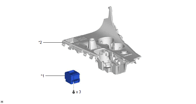
| *1 | BRAKE HOLD SWITCH (ELECTRIC PARKING BRAKE SWITCH ASSEMBLY) | *2 | CONSOLE PANEL SUB-ASSEMBLY |
Removal
REMOVAL
PROCEDURE
1. PRECAUTION
Click here .gif)
2. REMOVE CONSOLE PANEL SUB-ASSEMBLY
Click here
3. REMOVE BRAKE HOLD SWITCH (ELECTRIC PARKING BRAKE SWITCH ASSEMBLY)
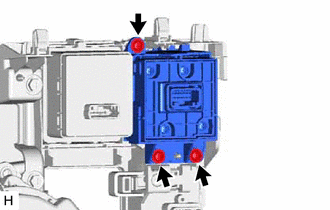
| (a) Remove the 3 screws and brake hold switch (electric parking brake switch assembly). |
|
Inspection
INSPECTION
PROCEDURE
1. INSPECT BRAKE HOLD SWITCH (ELECTRIC PARKING BRAKE SWITCH ASSEMBLY)
| (a) Make sure that there is no looseness in the locking part and the connecting part of the connector. |
|
(b) Disconnect the brake hold switch (electric parking brake switch assembly) connector.
(c) Check both the connector case and the terminal for deformation and corrosion.
OK:
No deformation or corrosion.
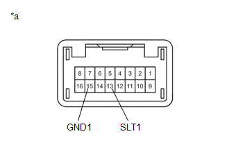
(d) Measure the resistance according to the value(s) in the table below.
Standard Resistance:
| Tester Connection | Condition | Specified Condition |
|---|---|---|
| 13 (SLT1) - 15 (GND1) | Switch pushed | Below 1 Ω |
| 13 (SLT1) - 15 (GND1) | Switch not pushed | 10 kΩ or higher |
If the result is not as specified, replace the brake hold switch (electric parking brake switch assembly).
Installation
INSTALLATION
PROCEDURE
1. INSTALL BRAKE HOLD SWITCH (ELECTRIC PARKING BRAKE SWITCH ASSEMBLY)
(a) Install the brake hold switch (electric parking brake switch assembly) with the 3 screws.
2. INSTALL CONSOLE PANEL SUB-ASSEMBLY
Click here .gif)
 Installation
INSTALLATION CAUTION / NOTICE / HINT HINT: The parking brake indicator light blinks (red) when the engine switch is turned on after replacing the brake actuator assembly. Operate the electric parking ...
 Brake Pedal Load Sensing Switch
On-vehicle InspectionON-VEHICLE INSPECTION PROCEDURE 1. INSPECT BRAKE PEDAL SUPPORT ASSEMBLY (a) Make sure that there is no looseness in the locking part and the connecting part of the connector. ...
Other materials:
Lexus RX (RX 350L, RX450h) 2016-2026 Repair Manual > Quarter Trim Speaker (w/ Rear No. 2 Seat): Removal
REMOVAL CAUTION / NOTICE / HINT HINT:
Use the same procedure for the RH side and LH side.
The following procedure is for the LH side.
PROCEDURE 1. REMOVE REAR NO. 2 SEAT ASSEMBLY Click here 2. REMOVE REAR DOOR SCUFF PLATE Click here 3. REMOVE REAR DOOR INSIDE SCUFF PLATE Click here 4 ...
Lexus RX (RX 350L, RX450h) 2016-2026 Repair Manual > 2gr-fks (engine Control): Relay
On-vehicle InspectionON-VEHICLE INSPECTION PROCEDURE 1. INSPECT INJECTOR RELAY (INJ) (a) Measure the resistance according to the value(s) in the table below. Standard Resistance: Tester Connection Condition Specified Condition 3 - 5 Battery voltage not applied between terminals 1 and ...
Lexus RX (RX 350L, RX450h) 2016-{YEAR} Owners Manual
- For your information
- Pictorial index
- For safety and security
- Instrument cluster
- Operation of each component
- Driving
- Lexus Display Audio system
- Interior features
- Maintenance and care
- When trouble arises
- Vehicle specifications
- For owners
Lexus RX (RX 350L, RX450h) 2016-{YEAR} Repair Manual

0.0093