Lexus RX (RX 350L, RX450h) 2016-2026 Repair Manual: Terminals Of Ecu
TERMINALS OF ECU
TERMINALS OF ECU
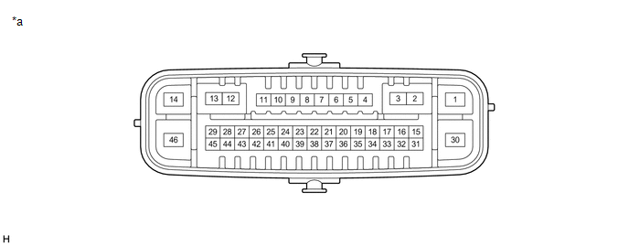
| *a | Component without harness connected (Skid Control ECU (Brake Actuator Assembly)) | - | - |
| Terminal No. (Symbol) | Terminal Description |
|---|---|
| 1 (GND1) | Skid control ECU (brake actuator assembly) ground |
| 2 | - |
| 3 | - |
| 4 (RL-) | Rear wheel speed LH (-) signal input |
| 5 (RL+) | Rear wheel speed LH (+) power supply output |
| 6 (FR-) | Front wheel speed RH (-) signal input |
| 7 (FR+) | Front wheel speed RH (+) power supply output |
| 8 | - |
| 9 (CSW) | VSC OFF switch (combination switch assembly) input |
| 10 | - |
| 11 (STP) | Stop light switch assembly input |
| 12 | - |
| 13 | - |
| 14 (+BS) | Solenoid relay power supply |
| 15 | - |
| 16 | - |
| 17 | - |
| 18 (SP1) | Speed signal output for speedometer |
| 19 (RR-) | Rear wheel speed RH (-) signal input |
| 20 (RR+) | Rear wheel speed RH (+) power supply output |
| 21 (FL-) | Front wheel speed LH (-) signal input |
| 22 (FL+) | Front wheel speed LH (+) power supply output |
| 23 | - |
| 24 | - |
| 25 | - |
| 26 | - |
| 27 (CANH) | CAN communication line H |
| 28 (FSW+) | Brake pedal load sensing switch (brake pedal support assembly) input |
| 29 | - |
| 30 (GND2) | Pump motor ground |
| 31 | - |
| 32 (STPO) | Stop light control relay output |
| 33 | - |
| 34 | - |
| 35 (PKB) | Brake hold switch (electric parking brake switch assembly) input |
| 36 | - |
| 37 (STP2) | Stop light signal input |
| 38 | - |
| 39 | - |
| 40 | - |
| 41 | - |
| 42 | - |
| 43 (CANL) | CAN communication line L |
| 44 | - |
| 45 (IG1) | ECU power supply input |
| 46 (BM) | Motor relay power supply |
TERMINAL INSPECTION
(a) Disconnect the A41 connector and measure the voltage or resistance on the wire harness side.

| *a | Front view of wire harness connector (to Skid Control ECU (Brake Actuator Assembly)) | - | - |
HINT:
Voltage cannot be measured with the connector connected to the skid control (brake actuator assembly) as the connector is watertight.
| Terminal No. (Symbol) | Wiring Color | Terminal Description | Condition | Specified Condition |
|---|---|---|---|---|
| A41-1 (GND1) - Body ground | W-B - Body ground | Skid control ECU (brake actuator assembly) ground | 1 minute or more after disconnecting the cable from the negative (-) battery terminal | Below 1 Ω |
| A41-9 (CSW) - Body ground | P - Body ground | VSC OFF switch (combination switch assembly) input | VSC OFF switch (combination switch assembly) pressed and held → released | Below 1 Ω → 10 kΩ or higher |
| A41-11 (STP) - Body ground | B - Body ground | Stop light switch assembly input | Stop light switch assembly on → off (brake pedal depressed → released) | 8 to 14 V → Below 1.5 V |
| A41-14 (+BS) - Body ground | L - Body ground | Solenoid relay power supply | Always | 11 to 14 V |
| A41-18 (SP1) - Body ground | BE - Body ground | Speed signal output for speedometer | Engine switch on (IG) | 11 to 14 V |
| A41-28 (FSW+) - Body ground | W - Body ground | Brake pedal load sensing switch (brake pedal support assembly) input | Brake pedal depressed → released | 950 to 1050 Ω → 203 to 223 Ω |
| A41-30 (GND2) - Body ground | W-B - Body ground | Pump motor ground | 1 minute or more after disconnecting the cable from the negative (-) battery terminal | Below 1 Ω |
| A41-32 (STPO) - Body ground | B - Body ground | Semiconductor PWR integration ECU output | Engine switch on (IG) | 11 to 14 V |
| A41-35 (PKB) - Body ground | R - Body ground | Brake hold switch (electric parking brake switch assembly) input | Brake hold switch (electric parking brake switch assembly) pressed and held → released | Below 1 Ω → 10 kΩ or higher |
| A41-37 (STP2) - Body ground | P - Body ground | Stop light signal input | Brake pedal depressed → released | 8 to 14 V → Below 1.5 V |
| A41-45 (IG1) - Body ground | V - Body ground | ECU power supply input | Engine switch on (IG) | 11 to 14 V |
| A41-46 (BM) - Body ground | R - Body ground | Motor relay power supply | Always | 11 to 14 V |
 Problem Symptoms Table
PROBLEM SYMPTOMS TABLE If there are no DTCs output and the problem still occurs, check the suspected areas for each problem symptom in the order given in the following table and proceed to the relevan ...
 Diagnosis System
DIAGNOSIS SYSTEM DESCRIPTION When troubleshooting a vehicle with the diagnosis system, the only difference from the usual troubleshooting procedure is connecting the Techstream to the vehicle and read ...
Other materials:
Lexus RX (RX 350L, RX450h) 2016-2026 Repair Manual > Can Communication System: Suspension Control ECU Communication Stop Mode
DESCRIPTION Detection Item Symptom Trouble Area Suspension Control ECU Communication Stop Mode Either condition is met:
"Suspension Control (Air Suspension)" is not displayed on the CAN Bus Check screen of the Techstream.
Click here
Communication system DTCs (DTCs that start w ...
Lexus RX (RX 350L, RX450h) 2016-2026 Repair Manual > Blind Spot Monitor System: Short to GND in Outer Mirror Indicator(Master) (C1AB2)
DESCRIPTION This DTC is stored when the blind spot monitor sensor LH detects a short to ground in the outer rear view mirror indicator LH. DTC No. Detection Item DTC Detection Condition Trouble Area C1AB2 Short to GND in Outer Mirror Indicator(Master) Both of the following conditio ...
Lexus RX (RX 350L, RX450h) 2016-{YEAR} Owners Manual
- For your information
- Pictorial index
- For safety and security
- Instrument cluster
- Operation of each component
- Driving
- Lexus Display Audio system
- Interior features
- Maintenance and care
- When trouble arises
- Vehicle specifications
- For owners
Lexus RX (RX 350L, RX450h) 2016-{YEAR} Repair Manual

0.012