Lexus RX (RX 350L, RX450h) 2016-2025 Repair Manual: Brake Pressure Sensor "A" Circuit Voltage Above Threshold (C054017)
DESCRIPTION
| DTC No. | Detection Item | DTC Detection Condition | Trouble Area |
|---|---|---|---|
| C054017 | Brake Pressure Sensor "A" Circuit Voltage Above Threshold | When vehicle speed exceeds 3 km/h (2 mph) and stop light switch assembly is OFF, master cylinder pressure continuously exceeds 1.764 MPa (18.0 kgf/cm2, 255 psi) for 5 seconds or more. |
|
WIRING DIAGRAM
Click here .gif)
CAUTION / NOTICE / HINT
NOTICE:
- Inspect the fuses for circuits related to this system before performing the following procedure.
-
After replacing the skid control ECU (brake actuator assembly), perform "Calibration".
Click here
PROCEDURE
| 1. | CLEAR DTC |
(a) Connect the Techstream to the DLC3.
(b) Turn the engine switch on (IG).
(c) Operate the Techstream to clear the codes. Enter the following menus: Chassis / Brake/EPB / Trouble Codes.
Chassis > Brake/EPB > Clear DTCs(d) Press the DTC clear button.
(e) Turn the engine switch off.
|
.gif)
| 2. | RECONFIRM DTC |
(a) Start the engine.
(b) Perform a road test.
(c) Read the DTCs following the prompts on the Techstream. Enter the following menus: Chassis / Brake/EPB / Trouble Codes.
Chassis > Brake/EPB > Trouble Codes(d) Check if the same DTC is output.
| Result | Proceed to |
|---|---|
| DTC C054017 is output | A |
| DTCs C054017 and P057113 are output | B |
| B | .gif) | GO TO DTC CHART (P057113) |
|
| 3. | READ VALUE USING TECHSTREAM (STOP LIGHT SWITCH ASSEMBLY) |
(a) Enter the following menus: Chassis / Brake/EPB / Data List.
Chassis > Brake/EPB > Data List| Tester Display | Measurement Item | Range | Normal Condition | Diagnostic Note |
|---|---|---|---|---|
| Stop Light SW | Stop light switch assembly (STP terminal input) | OFF / ON | OFF: Brake pedal released ON: Brake pedal depressed | HINT: The brake pedal state is determined using the voltage at terminal STP |
| Tester Display |
|---|
| Stop Light SW |
(b) Check that the stop light switch assembly condition observed on the Techstream changes according to brake pedal operation.
OK:
The Techstream displays OFF / ON according to brake pedal operation.
| NG | | GO TO STEP 7 |
|
| 4. | READ VALUE USING TECHSTREAM (MASTER CYLINDER SENSOR) |
(a) Enter the following menus: Chassis / Brake/EPB / Data List.
Chassis > Brake/EPB > Data List| Tester Display | Measurement Item | Range | Normal Condition | Diagnostic Note |
|---|---|---|---|---|
| Master Cylinder Sensor 1 | Master cylinder pressure sensor pressure (value detected by ECU) | Min.: -1.00 MPa Max.: 23.99 MPa | Brake pedal released: -1.00 to 0.00 MPa | Reading increases when brake pedal is depressed |
| Tester Display |
|---|
| Master Cylinder Sensor 1 |
(b) Start the engine.
(c) Check the value of Data List item Master Cylinder Sensor 1 when the brake pedal is released.
OK:
The value of Data List item Master Cylinder 1 is within standard range.
| NG | | REPLACE BRAKE ACTUATOR ASSEMBLY |
|
| 5. | CLEAR DTC |
(a) Operate the Techstream to clear the codes. Enter the following menus: Chassis / Brake/EPB / Trouble Codes.
Chassis > Brake/EPB > Clear DTCs(b) Press the DTC clear button.
(c) Turn the engine switch off.
|
| 6. | RECONFIRM DTC |
(a) Start the engine.
(b) Drive the vehicle and perform a braking test (decelerate the vehicle by depressing the brake pedal).
(c) Read the DTCs following the prompts on the Techstream. Enter the following menus: Chassis / Brake/EPB / Trouble Codes.
Chassis > Brake/EPB > Trouble Codes(d) Check if the same DTC is output.
| Result | Proceed to |
|---|---|
| DTC C054017 is not output. | A |
| DTC C054017 is output. | B |
| A | | USE SIMULATION METHOD TO CHECK |
| B | | REPLACE BRAKE ACTUATOR ASSEMBLY |
| 7. | CHECK STOP LIGHT SWITCH ASSEMBLY INSTALLATION |
(a) Turn the engine switch off.
(b) Check the stop light switch assembly installation.
Click here
OK:
The stop light switch assembly installation are normal.
| NG | | INSTALL STOP LIGHT SWITCH ASSEMBLY CORRECTLY |
|
| 8. | INSPECT STOP LIGHT SWITCH ASSEMBLY |
(a) Inspect the stop light switch assembly.
Click here
OK:
The stop light switch assembly is normal.
| NG | | REPLACE STOP LIGHT SWITCH ASSEMBLY |
|
| 9. | CHECK HARNESS AND CONNECTOR (STP TERMINAL) |
| (a) Make sure that there is no looseness at the locking part and the connecting part of the connectors. OK: The connector is securely connected. |
|
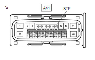
(b) Disconnect the A41 skid control ECU (brake actuator assembly) connector.
(c) Check both the connector case and the terminals for deformation and corrosion.
OK:
No deformation or corrosion.
(d) Measure the voltage according to the value(s) in the table below.
Standard Voltage:
| Tester Connection | Condition | Specified Condition |
|---|---|---|
| A41-11 (STP) - Body ground | Stop light switch assembly on (Brake pedal depressed) | 8 to 14 V |
| A41-11 (STP) - Body ground | Stop light switch assembly off (Brake pedal released) | Below 1.5 V |
| OK | | REPLACE BRAKE ACTUATOR ASSEMBLY |
| NG | | REPAIR OR REPLACE HARNESS OR CONNECTOR |
 Brake Pressure Sensor "A" Circuit Voltage Below Threshold (C054016,C05401C,C05401F,C054029,C05402A,C054031,C054049,C054096)
DESCRIPTION DTC No. Detection Item DTC Detection Condition Trouble Area C054016 Brake Pressure Sensor "A" Circuit Voltage Below Threshold Master cylinder pressure is below -0.744 MPa ...
 Brake System Control Module "A" Internal Electronic Failure (C059749,...,C13C91C)
DESCRIPTION The solenoid relay and solenoid valves are built into the brake actuator assembly. The solenoid valves control the brake fluid pressure at each wheel cylinder. When this DTC is stored, the ...
Other materials:
Lexus RX (RX 350L, RX450h) 2016-2025 Repair Manual > Steering Lock System: Dtc Check / Clear
DTC CHECK / CLEAR NOTICE:
The steering lock ECU (steering lock actuator or upper bracket assembly) does not store history DTCs. If any DTCs are output, confirm and record them as soon as possible. Do not turn the engine switch off or clear the DTCs until the DTCs are confirmed and recorded.
DTC ...
Lexus RX (RX 350L, RX450h) 2016-2025 Repair Manual > Glove Box Light: Installation
INSTALLATION PROCEDURE 1. INSTALL GLOVE BOX LIGHT ASSEMBLY (a) Turn the glove box light assembly as shown in the illustration to install it. Install in this Direction 2. INSTALL GLOVE COMPARTMENT DOOR ASSEMBLY Click here 3. INSTALL LOWER NO. 1 INSTRUMENT PANEL FINISH PANEL Click here ...
Lexus RX (RX 350L, RX450h) 2016-{YEAR} Owners Manual
- For your information
- Pictorial index
- For safety and security
- Instrument cluster
- Operation of each component
- Driving
- Lexus Display Audio system
- Interior features
- Maintenance and care
- When trouble arises
- Vehicle specifications
- For owners
Lexus RX (RX 350L, RX450h) 2016-{YEAR} Repair Manual

0.014