Lexus RX (RX 350L, RX450h) 2016-2025 Repair Manual: Steering Angle Sensor Supply Voltage Circuit Circuit Short to Ground or Open (C14FE14)
DESCRIPTION
This DTC is stored when the skid control ECU (brake actuator assembly) receives a power supply malfunction signal from the steering angle sensor.
| DTC No. | Detection Item | DTC Detection Condition | Trouble Area |
|---|---|---|---|
| C14FE14 | Steering Angle Sensor Supply Voltage Circuit Circuit Short to Ground or Open | When the +BS terminal voltage is from 9.5 to 17.4 V, a steering angle sensor power supply malfunction signal is received from the steering angle sensor. |
|
WIRING DIAGRAM
Click here .gif)
CAUTION / NOTICE / HINT
NOTICE:
Inspect the fuses for circuits related to this system before performing the following procedure.
PROCEDURE
| 1. | CLEAR DTC |
(a) Operate the Techstream to clear the codes. Enter the following menus: Chassis / Brake/EPB / Trouble Codes.
Chassis > Brake/EPB > Clear DTCs(b) Press the DTC clear button.
(c) Turn the engine switch off.
|
.gif)
| 2. | RECONFIRM DTC |
(a) Start the engine.
(b) Perform a road test.
(c) Read the DTCs following the prompts on the Techstream. Enter the following menus: Chassis / Brake/EPB / Trouble Codes.
Chassis > Brake/EPB > Trouble Codes(d) Check if the same DTC is output.
| Result | Proceed to |
|---|---|
| DTC C14FE14 is not output. | A |
| DTC C14FE14 is output. | B |
| A | .gif) | USE SIMULATION METHOD TO CHECK |
|
| 3. | CHECK HARNESS AND CONNECTOR (IG1 TERMINAL) |
| (a) Make sure that there is no looseness at the locking part and the connecting part of the connectors. OK: The connector is securely connected. |
|
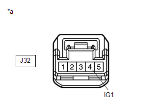
(b) Disconnect the J32 steering angle sensor connector.
(c) Check both the connector case and the terminals for deformation and corrosion.
OK:
No deformation or corrosion.
(d) Turn the engine switch on (IG).
(e) Measure the voltage according to the value(s) in the table below.
Standard Voltage:
| Tester Connection | Condition | Specified Condition |
|---|---|---|
| J32-4 (IG1) - Body ground | Engine switch on (IG) | 11 to 14 V |
| NG | | REPAIR OR REPLACE HARNESS OR CONNECTOR |
|
| 4. | CHECK HARNESS AND CONNECTOR (BAT TERMINAL) |
| (a) Turn the engine switch off. |
|
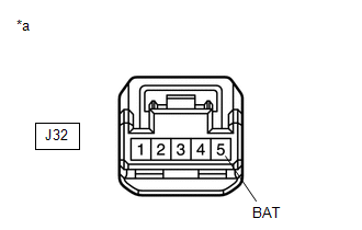
(b) Measure the voltage according to the value(s) in the table below.
Standard Voltage:
| Tester Connection | Condition | Specified Condition |
|---|---|---|
| J32-5 (BAT) - Body ground | Always | 11 to 14 V |
| NG | | REPAIR OR REPLACE HARNESS OR CONNECTOR |
|
| 5. | CHECK HARNESS AND CONNECTOR (GND TERMINAL) |
(a) Measure the resistance according to the value(s) in the table below.
Standard Resistance:
| Tester Connection | Condition | Specified Condition |
|---|---|---|
| J32-1 (ESS) - Body ground | 1 minute or more after disconnecting the cable from the negative (-) battery terminal | Below 1 Ω |
| OK | | REPLACE STEERING ANGLE SENSOR |
| NG | | REPAIR OR REPLACE HARNESS OR CONNECTOR |
 Left Rear Wheel Speed Sensor Supply Voltage Circuit Short to Ground or Open (C14E614,C14E914)
DESCRIPTION Refer to DTC C050C1F. Click here DTC No. Detection Item DTC Detection Condition Trouble Area C14E614 Left Rear Wheel Speed Sensor Supply Voltage Circuit Short to Ground or ...
 Brake Switch "A" Circuit Short to Ground (P057111)
DESCRIPTION The skid control ECU (brake actuator assembly) inputs the stop light signal and brake operation condition. When the brake pedal is depressed and the stop light switch signal is not input, ...
Other materials:
Lexus RX (RX 350L, RX450h) 2016-2025 Repair Manual > Wireless Door Lock Control System: Diagnosis System
DIAGNOSIS SYSTEM DESCRIPTION The main body ECU (multiplex network body ECU) stores DTCs when malfunctions occur. The diagnostic system allows for reading of the DTCs from the DLC3. Use the Techstream to check for malfunctions and perform repairs. CHECK DLC3 (a) Check the DLC3. Click here INSPECT B ...
Lexus RX (RX 350L, RX450h) 2016-2025 Repair Manual > Air Conditioning System: Check Mode Procedure
CHECK MODE PROCEDURE REFRIGERANT SHORTAGE CHECK IN NORMAL OPERATION (CHECK A/C SWITCH INDICATOR AND DTC) (a) Start the engine. (b) Check that the A/C switch indicator remains on when the following conditions are met. *a A/C Switch (Multi-display) Measurement Condition: Item Condition ...
Lexus RX (RX 350L, RX450h) 2016-{YEAR} Owners Manual
- For your information
- Pictorial index
- For safety and security
- Instrument cluster
- Operation of each component
- Driving
- Lexus Display Audio system
- Interior features
- Maintenance and care
- When trouble arises
- Vehicle specifications
- For owners
Lexus RX (RX 350L, RX450h) 2016-{YEAR} Repair Manual

0.0199