Lexus RX (RX 350L, RX450h) 2016-2026 Repair Manual: Brake Switch "A" Circuit Short to Ground (P057111)
DESCRIPTION
The skid control ECU (brake actuator assembly) inputs the stop light signal and brake operation condition.
When the brake pedal is depressed and the stop light switch signal is not input, this DTC is output.
| DTC No. | Detection Item | DTC Detection Condition | Trouble Area |
|---|---|---|---|
| P057111 | Brake Switch "A" Circuit Short to Ground | Either of the following is detected:
|
|
| Vehicle Condition | |||
|---|---|---|---|
| Pattern 1 | Pattern 2 | ||
| Diagnosis Condition | +BS terminal voltage 9.5 V or higher | ○ | - |
| Malfunction Status | When the brake pedal load sensing switch is ON, the stop light switch signal is input continuously for 2 seconds or more with the master cylinder pressure at 2 MPa (20.4 kgf/cm2) or higher and the deceleration calculated from the vehicle speed at 0.2 G or higher. | ○ | - |
| After a master cylinder pressure of more than 1.764 MPa (18.0 kgf/cm2) is detected for 5 seconds or more continuously at a vehicle speed below 3 km/h (2 mph) with the stop light switch assembly off, the master cylinder pressure exceeds 1.764 MPa (18.0 kgf/cm2) for 1 second or more continuously while and the stop light switch assembly signal is not received when the vehicle decelerates from over 35 km/h (22 mph) to 3 km/h (2 mph) | - | ○ | |
| Detection Time | 2 seconds or more | - | |
| Number of Trips | 1 trip | 1 trip | |
HINT:
DTC will be output when conditions for either of the patterns in the table above are met.
WIRING DIAGRAM
-
Refer to DTC C004013.
Click here

-
Refer to DTC P057113.
Click here
CAUTION / NOTICE / HINT
NOTICE:
- Inspect the fuses for circuits related to this system before performing the following procedure.
-
After replacing the skid control ECU (brake actuator assembly), perform "Calibration".
Click here
PROCEDURE
| 1. | CHECK BRAKE PEDAL HEIGHT AND STOP LIGHT SWITCH ASSEMBLY INSTALLATION |
(a) Check the brake pedal height and stop light switch assembly installation.
Click here
OK:
The brake pedal height and stop light switch assembly installation are normal.
HINT:
If the on/off status of the stop light switch assembly and the pressure increase information from the master cylinder pressure sensor do not match due to an improperly installed brake pedal or stop light switch assembly, this DTC may be stored. Therefore, be sure to check the installation condition of the pedal and stop light switch assembly before inspecting the input signals and other related parts.
| NG |  | ADJUST BRAKE PEDAL HEIGHT OR STOP LIGHT SWITCH ASSEMBLY INSTALLATION |
|
.gif)
| 2. | CHECK STOP LIGHT OPERATION |
(a) Check that the stop lights come on when the brake pedal is depressed, and go off when the brake pedal is released.
OK:
| Condition | Illumination Condition |
|---|---|
| Brake pedal depressed. | On |
| Brake pedal released. | Off |
| NG | | GO TO STEP 11 |
|
| 3. | READ VALUE USING TECHSTREAM (STOP LIGHT SW) |
(a) Connect the Techstream to the DLC3.
(b) Turn the engine switch on (IG).
(c) Enter the following menus: Chassis / Brake/EPB / Data List.
Chassis > Brake/EPB > Data List| Tester Display | Measurement Item | Range | Normal Condition | Diagnostic Note |
|---|---|---|---|---|
| Stop Light SW | Stop light switch assembly (STP terminal input) | OFF / ON | OFF: Brake pedal released ON: Brake pedal depressed | HINT: The brake pedal state is determined using the voltage at terminal STP |
| Brake Pedal Load Sensing SW | Brake pedal load sensing switch | OFF / ON | OFF: Brake pedal released ON: Brake pedal depressed | - |
| Tester Display |
|---|
| Stop Light SW |
| Brake Pedal Load Sensing SW |
(d) Check that the stop light switch display and brake pedal load sensing switch display observed on the Techstream change according to brake pedal operation.
OK:
The Techstream displays OFF / ON according to brake pedal operation.
(e) Slowly depress the brake pedal, and check when the stop light switch assembly and brake pedal load sensing switch turn on.
OK:
First the stop light switch assembly should turn on, and then the brake pedal load sensing switch should turn on.
| Result | Proceed to |
|---|---|
| OK | A |
| NG (The stop light switch assembly does not turn on.) | B |
| NG (Turning on of the brake pedal load sensing switch is not confirmed.) | C |
| NG (The brake pedal load sensing switch turns on first.) | D |
| B | | GO TO STEP 6 |
| C | | GO TO STEP 10 |
| D | | REPLACE BRAKE PEDAL SUPPORT ASSEMBLY |
|
| 4. | CLEAR DTC |
(a) Operate the Techstream to clear the codes. Enter the following menus: Chassis / Brake/EPB / Trouble Codes.
Chassis > Brake/EPB > Clear DTCs(b) Press the DTC clear button.
(c) Turn the engine switch off.
|
| 5. | RECONFIRM DTC |
(a) Start the engine.
(b) Perform a road test.
(c) Read the DTCs following the prompts on the Techstream. Enter the following menus: Chassis / Brake/EPB / Trouble Codes.
Chassis > Brake/EPB > Trouble Codes(d) Check if the same DTC is output.
| Result | Proceed to |
|---|---|
| DTC P057111 is not output. | A |
| DTC P057111 is output. | B |
| A | | USE SIMULATION METHOD TO CHECK |
| B | | REPLACE BRAKE ACTUATOR ASSEMBLY |
| 6. | CHECK HARNESS AND CONNECTOR (STP TERMINAL) |
| (a) Turn the engine switch off. |
|

(b) Make sure that there is no looseness at the locking part and the connecting part of the connectors.
OK:
The connector is securely connected.
(c) Disconnect the A41 skid control ECU (brake actuator assembly) connector.
(d) Check both the connector case and the terminals for deformation and corrosion.
OK:
No deformation or corrosion.
(e) Measure the voltage according to the value(s) in the table below.
Standard Voltage:
| Tester Connection | Condition | Specified Condition |
|---|---|---|
| A41-11 (STP) - Body ground | Stop light switch assembly on (Brake pedal depressed) | 8 to 14 V |
| A41-11 (STP) - Body ground | Stop light switch assembly off (Brake pedal released) | Below 1.5 V |
| NG | | REPAIR OR REPLACE HARNESS OR CONNECTOR |
|
| 7. | CLEAR DTC |
(a) Reconnect the A41 skid control ECU (brake actuator assembly) connector.
(b) Operate the Techstream to clear the codes. Enter the following menus: Chassis / Brake/EPB / Trouble Codes.
Chassis > Brake/EPB > Clear DTCs(c) Press the DTC clear button.
(d) Turn the engine switch off.
|
| 8. | RECONFIRM DTC |
(a) Start the engine.
(b) Perform a road test.
(c) Read the DTCs following the prompts on the Techstream. Enter the following menus: Chassis / Brake/EPB / Trouble Codes.
Chassis > Brake/EPB > Trouble Codes(d) Check if the same DTC is output.
| Result | Proceed to |
|---|---|
| DTC P057111 is not output. | A |
| DTC P057111 is output. | B |
| B | | REPLACE BRAKE ACTUATOR ASSEMBLY |
|
| 9. | INSPECT BRAKE PEDAL SUPPORT ASSEMBLY |
| (a) Turn the engine switch off. |
|
(b) Make sure that there is no looseness at the locking part and the connecting part of the connectors.
OK:
The connector is securely connected.
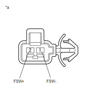
(c) Disconnect the A51 brake pedal load sensing switch (brake pedal support assembly) connector.
NOTICE:
- Do not remove the brake pedal load sensing switch from the brake pedal support assembly.
- When there is a malfunction in the brake pedal load sensing switch, replace the brake pedal support assembly.
(d) Check both the connector case and the terminals for deformation and corrosion.
OK:
No deformation or corrosion.
(e) Measure the resistance according to the value(s) in the table below.
Standard Resistance:
| Tester Connection | Condition | Specified Condition |
|---|---|---|
| 2 (FSW+) - 1 (FSW-) | Brake pedal load sensing switch off (Brake pedal depressed) | 950 to 1050 Ω |
| 2 (FSW+) - 1 (FSW-) | Brake pedal load sensing switch on (Brake pedal released) | 203 to 223 Ω |
| OK | | GO TO STEP 10 |
| NG | | REPLACE BRAKE PEDAL SUPPORT ASSEMBLY |
| 10. | CHECK HARNESS AND CONNECTOR (BRAKE PEDAL SUPPORT ASSEMBLY - BRAKE ACTUATOR ASSEMBLY) |
(a) Make sure that there is no looseness at the locking part and the connecting part of the connectors.
OK:
The connector is securely connected.
(b) Disconnect the A41 skid control ECU (brake actuator assembly) connector.
(c) Disconnect the A51 brake pedal load sensing switch (brake pedal support assembly) connector.
(d) Check both the connector case and the terminals for deformation and corrosion.
OK:
No deformation or corrosion.
(e) Measure the resistance according to the value(s) in the table below.
Standard Resistance:
| Tester Connection | Condition | Specified Condition |
|---|---|---|
| A51-2 (FSW+) - A41-28 (FSW+) | Always | Below 1 Ω |
| A51-2 (FSW+) or A41-28 (FSW+) - Body ground | Always | 10 kΩ or higher |
| A51-1 (FSW-) - Body ground | 1 minute or more after disconnecting the cable from the negative (-) battery terminal | Below 1 Ω |
| OK | | REPLACE BRAKE ACTUATOR ASSEMBLY |
| NG | | REPAIR OR REPLACE HARNESS OR CONNECTOR |
| 11. | INSPECT STOP LIGHT SWITCH ASSEMBLY |
(a) Inspect the stop light switch assembly.
Click here
OK:
The stop light switch assembly is normal.
| NG | | REPLACE STOP LIGHT SWITCH ASSEMBLY |
|
| 12. | CHECK HARNESS AND CONNECTOR (STP TERMINAL) |
| (a) Turn the engine switch off. |
|
(b) Make sure that there is no looseness at the locking part and the connecting part of the connectors.
OK:
The connector is securely connected.
(c) Disconnect the A41 skid control ECU (brake actuator assembly) connector.
(d) Check both the connector case and the terminals for deformation and corrosion.
OK:
No deformation or corrosion.
(e) Measure the voltage according to the value(s) in the table below.
Standard Voltage:
| Tester Connection | Condition | Specified Condition |
|---|---|---|
| A41-11 (STP) - Body ground | Stop light switch assembly on (Brake pedal depressed) | 8 to 14 V |
| A41-11 (STP) - Body ground | Stop light switch assembly off (Brake pedal released) | Below 1.5 V |
| NG | | REPAIR OR REPLACE HARNESS OR CONNECTOR |
|
| 13. | CLEAR DTC |
(a) Reconnect the A41 skid control ECU (brake actuator assembly) connector.
(b) Connect the Techstream to the DLC3.
(c) Turn the engine switch on (IG).
(d) Operate the Techstream to clear the codes. Enter the following menus: Chassis / Brake/EPB / Trouble Codes.
Chassis > Brake/EPB > Clear DTCs(e) Press the DTC clear button.
(f) Turn the engine switch off.
|
| 14. | RECONFIRM DTC |
(a) Start the engine.
(b) Perform a road test.
(c) Read the DTCs following the prompts on the Techstream. Enter the following menus: Chassis / Brake/EPB / Trouble Codes.
Chassis > Brake/EPB > Trouble Codes(d) Check if the same DTC is output.
| Result | Proceed to |
|---|---|
| DTC P057111 is not output. | A |
| DTC P057111 is output. | B |
| A | | USE SIMULATION METHOD TO CHECK |
| B | | REPLACE BRAKE ACTUATOR ASSEMBLY |
 Steering Angle Sensor Supply Voltage Circuit Circuit Short to Ground or Open (C14FE14)
DESCRIPTION This DTC is stored when the skid control ECU (brake actuator assembly) receives a power supply malfunction signal from the steering angle sensor. DTC No. Detection Item DTC Detectio ...
 Brake Switch "A" Circuit Open (P057113)
DESCRIPTION The skid control ECU (brake actuator assembly) detects the brake operating conditions through a signal transmitted by the stop light switch. The skid control ECU incorporates a circuit to ...
Other materials:
Lexus RX (RX 350L, RX450h) 2016-2026 Repair Manual > Washer Nozzle(for Front Side): Components
COMPONENTS ILLUSTRATION *1 WASHER NOZZLE SUB-ASSEMBLY - - ● Non-reusable part - - ...
Lexus RX (RX 350L, RX450h) 2016-2026 Repair Manual > Headup Display System: Precaution
PRECAUTION PRECAUTION FOR DISCONNECTING CABLE FROM NEGATIVE BATTERY TERMINAL NOTICE: When disconnecting the cable from the negative (-) battery terminal, initialize the following systems after the cable is reconnected. System Name See Procedure Lane Control System Pre-collision Sys ...
Lexus RX (RX 350L, RX450h) 2016-{YEAR} Owners Manual
- For your information
- Pictorial index
- For safety and security
- Instrument cluster
- Operation of each component
- Driving
- Lexus Display Audio system
- Interior features
- Maintenance and care
- When trouble arises
- Vehicle specifications
- For owners
Lexus RX (RX 350L, RX450h) 2016-{YEAR} Repair Manual

0.0096