Lexus RX (RX 350L, RX450h) 2016-2026 Repair Manual: Brake Switch "A" Circuit Open (P057113)
DESCRIPTION
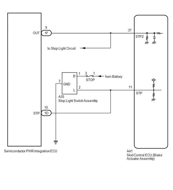
The skid control ECU (brake actuator assembly) detects the brake operating conditions through a signal transmitted by the stop light switch.
The skid control ECU incorporates a circuit to detect an open circuit.
This DTC is output when an open circuit is detected in the stop light signal input line.
| DTC No. | Detection Item | DTC Detection Condition | Trouble Area |
|---|---|---|---|
| P057113 | Brake Switch "A" Circuit Open | When the +BS terminal voltage is 9.5 V or more, an open is detected in the STP terminal circuit for 0.3 seconds or more and the stop light drive output (STPO) is off for 0.1 seconds or more. |
|
WIRING DIAGRAM

CAUTION / NOTICE / HINT
NOTICE:
- Inspect the fuses for circuits related to this system before performing the following procedure.
-
After replacing the skid control ECU (brake actuator assembly), perform "Calibration".
Click here
.gif)
PROCEDURE
| 1. | READ VALUE USING TECHSTREAM (STOP LIGHT SW) |
(a) Connect the Techstream to the DLC3.
(b) Turn the engine switch on (IG).
(c) Enter the following menus: Chassis / Brake/EPB / Data List.
Chassis > Brake/EPB > Data List| Tester Display | Measurement Item | Range | Normal Condition | Diagnostic Note |
|---|---|---|---|---|
| Stop Light SW | Stop light switch assembly (STP terminal input) | OFF / ON | OFF: Brake pedal released ON: Brake pedal depressed | HINT: The brake pedal state is determined using the voltage at terminal STP |
| Tester Display |
|---|
| Stop Light SW |
(d) Check that the stop light switch display observed on the Techstream changes according to brake pedal operation.
OK:
The Techstream displays OFF / ON according to brake pedal operation.
| NG | .gif) | GO TO STEP 4 |
|
| 2. | CLEAR DTC |
(a) Operate the Techstream to clear the codes. Enter the following menus: Chassis / Brake/EPB / Trouble Codes.
Chassis > Brake/EPB > Clear DTCs(b) Press the DTC clear button.
(c) Turn the engine switch off.
|
| 3. | RECONFIRM DTC |
(a) Turn the engine switch on (IG).
(b) Read the DTCs following the prompts on the Techstream. Enter the following menus: Chassis / Brake/EPB / Trouble Codes.
Chassis > Brake/EPB > Trouble Codes(c) Check if the same DTC is output.
| Result | Proceed to |
|---|---|
| DTC P057113 is not output. | A |
| DTC P057113 is output. | B |
| A | .gif) | USE SIMULATION METHOD TO CHECK |
| B | .gif) | REPLACE BRAKE ACTUATOR ASSEMBLY |
| 4. | CHECK HARNESS AND CONNECTOR (STP TERMINAL) |
| (a) Turn the engine switch off. |
|
(b) Make sure that there is no looseness at the locking part and the connecting part of the connectors.
OK:
The connector is securely connected.
(c) Disconnect the A41 skid control ECU (brake actuator assembly) connector.
(d) Check both the connector case and the terminals for deformation and corrosion.
OK:
No deformation or corrosion.
(e) Measure the voltage according to the value(s) in the table below.
Standard Voltage:
| Tester Connection | Condition | Specified Condition |
|---|---|---|
| A41-11 (STP) - Body ground | Stop light switch assembly on (Brake pedal depressed) | 8 to 14 V |
| A41-11 (STP) - Body ground | Stop light switch assembly off (Brake pedal released) | Below 1.5 V |
| OK | .gif) | REPLACE BRAKE ACTUATOR ASSEMBLY |
| NG | .gif) | REPAIR OR REPLACE HARNESS OR CONNECTOR |
 Brake Switch "A" Circuit Short to Ground (P057111)
DESCRIPTION The skid control ECU (brake actuator assembly) inputs the stop light signal and brake operation condition. When the brake pedal is depressed and the stop light switch signal is not input, ...
 Control Module Communication Bus "B" Off Bus Off (U007488,U010087,U010187,U012587,U012687,U015187)
DESCRIPTION The skid control ECU (brake actuator assembly) receives signals from the ECM, steering angle sensor, yaw rate and acceleration sensor (for TFT Meter Type) and airbag sensor assembly via CA ...
Other materials:
Lexus RX (RX 350L, RX450h) 2016-2026 Repair Manual > Black Out Tape (for Front Door): Installation
INSTALLATION CAUTION / NOTICE / HINT HINT:
Use the same procedure for the RH side and LH side.
The following procedure is for the LH side.
PROCEDURE 1. REPAIR INSTRUCTION (a) Clean the vehicle body surface. (1) Using a heat light, heat the vehicle body surface. Heating Temperature Item ...
Lexus RX (RX 350L, RX450h) 2016-2026 Repair Manual > Door Control Receiver: Components
COMPONENTS ILLUSTRATION *A w/o Rear No. 2 Seat *B for TMC Made *C for TMMC Made - - *1 DECK BOARD ASSEMBLY *2 DECK SIDE TRIM BOX RH *3 REAR DECK FLOOR BOX *4 REAR FLOOR FINISH PLATE *5 REAR NO. 3 FLOOR BOARD *6 REAR NO. 4 FLOOR BOARD *7 TONNEAU ...
Lexus RX (RX 350L, RX450h) 2016-{YEAR} Owners Manual
- For your information
- Pictorial index
- For safety and security
- Instrument cluster
- Operation of each component
- Driving
- Lexus Display Audio system
- Interior features
- Maintenance and care
- When trouble arises
- Vehicle specifications
- For owners
Lexus RX (RX 350L, RX450h) 2016-{YEAR} Repair Manual
0.0088

.gif)
.png)