Lexus RX (RX 350L, RX450h) 2016-2026 Repair Manual: Brake Hold Standby Indicator Light Circuit
DESCRIPTION
The brake hold standby indicator light turns on if brake hold control is possible when the following conditions required for operation standby are met and the brake hold switch (electric parking brake switch assembly) is pressed while the engine switch is on (IG).
-
Conditions required for operation standby:
- The driver door is closed.
- The driver seat belt is fastened.
- The system is normal.
HINT:
If a malfunction occurs in one of the following systems, the brake hold operated indicator light will blink. If this occurs, perform troubleshooting on the malfunctioning system.
- Brake system
- Electric parking brake system
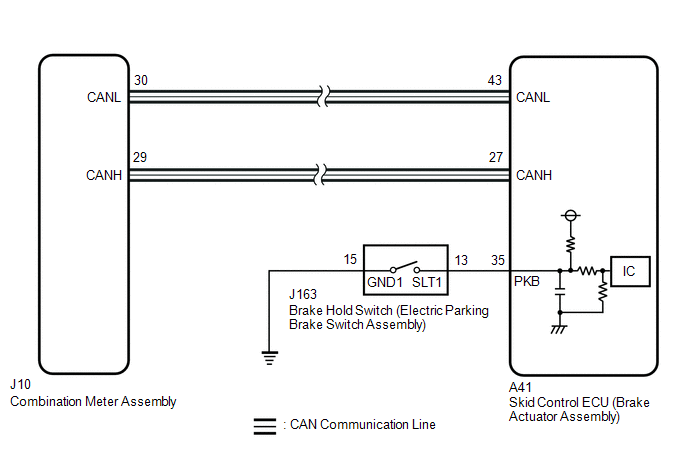
WIRING DIAGRAM
CAUTION / NOTICE / HINT
NOTICE:
After replacing the skid control ECU (brake actuator assembly), perform "Calibration".
Click here .gif)
PROCEDURE
| 1. | PRE-CHECK |
(a) If the brake hold standby indicator light does not illuminate even though the brake hold switch (electric parking brake switch assembly) is pushed, check that the brake hold function operation conditions are met.
- The driver door is closed.
- The driver seat belt is fastened.
- The system is normal.
HINT:
If a malfunction occurs in one of the following systems, the brake hold operated indicator light will blink. If this occurs, perform troubleshooting on the malfunctioning system.
- Brake system
- Electric parking brake system
|
.gif)
| 2. | INSPECT COMBINATION METER ASSEMBLY |
(a) Connect the Techstream to the DLC3.
(b) Turn the engine switch on (IG).
(c) Enter the following menus: Body Electrical /Combination Meter / Active Test.
(d) Perform the Active Test of the combination meter assembly using the Techstream.
Body Electrical > Combination Meter > Active Test| Tester Display |
|---|
| Indicat. Brake Hold |
(e) Check the combination meter assembly.
OK:
The brake hold standby indicator light turns on (flashes) or off in accordance with the Techstream operation.
| NG | .gif) | INSPECT METER / GAUGE SYSTEM |
|
| 3. | INSPECT ELECTRIC PARKING BRAKE SWITCH ASSEMBLY |
| (a) Turn the engine switch off. |
|
(b) Make sure that there is no looseness at the locking part and the connecting part of the connectors.
OK:
The connector is securely connected.
(c) Disconnect the J163 brake hold switch (electric parking brake switch assembly) connector.
(d) Check both the connector case and the terminals for deformation and corrosion.
OK:
No deformation or corrosion.
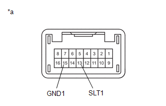
(e) Measure the resistance according to the value(s) in the table below.
Standard Resistance:
| Tester Connection | Condition | Specified Condition |
|---|---|---|
| 13 (SLT1) - 15 (GND1) | Switch pushed | Below 1 Ω |
| 13 (SLT1) - 15 (GND1) | Switch not pushed | 10 kΩ or higher |
| NG | | REPLACE ELECTRIC PARKING BRAKE SWITCH ASSEMBLY |
|
| 4. | CHECK HARNESS AND CONNECTOR (ELECTRIC PARKING BRAKE SWITCH ASSEMBLY - BRAKE ACTUATOR ASSEMBLY) |
(a) Make sure that there is no looseness at the locking part and the connecting part of the connectors.
OK:
The connector is securely connected.
(b) Disconnect the A41 skid control ECU (brake actuator assembly) connector.
(c) Check both the connector case and the terminals for deformation and corrosion.
OK:
No deformation or corrosion.
(d) Measure the resistance according to the value(s) in the table below.
Standard Resistance:
| Tester Connection | Condition | Specified Condition |
|---|---|---|
| J163-13 (SLT1) - A41-35 (PKB) | Always | Below 1 Ω |
| J163-13 (SLT1) or A41-35 (PKB) - Body ground | Always | 10 kΩ or higher |
| J163-15 (GND1) - Body ground | 1 minute or more after disconnecting the cable from the negative (-) battery terminal | Below 1 Ω |
| OK | | REPLACE BRAKE ACTUATOR ASSEMBLY |
| NG | | REPAIR OR REPLACE HARNESS OR CONNECTOR |
 Brake Hold Operated Indicator Light Circuit
DESCRIPTION The brake hold operated indicator light illuminates when the brake hold system is operating (vehicle stopped due to brake fluid pressure hold) and turns off when the brake hold system oper ...
 Slip Indicator Light Remains ON
DESCRIPTION This procedure is for troubleshooting when the slip indicator light remains on but no DTCs are output. The skid control ECU (brake actuator assembly) controls the slip indicator light in t ...
Other materials:
Lexus RX (RX 350L, RX450h) 2016-2026 Repair Manual > Smart Access System With Push-button Start (for Entry Function): Entry Interior Alarm does not Sound
DESCRIPTION The smart access system with push-button start (for Entry Function) uses the buzzer in the combination meter assembly (meter ECU) to perform various vehicle interior warnings. When the conditions of each warning are met, the certification ECU (smart key ECU assembly) sends a buzzer activ ...
Lexus RX (RX 350L, RX450h) 2016-2026 Repair Manual > Lane Control System: Diagnostic Trouble Code Chart
DIAGNOSTIC TROUBLE CODE CHART Lane Control System DTC No. Detection Item Link C1A7496 Steering Vibrator Component Internal Failure U010087 Lost Communication with ECM/PCM "A" Missing Message U012587 Lost Communication with Multi-axis Acceleration Sensor Module Miss ...
Lexus RX (RX 350L, RX450h) 2016-{YEAR} Owners Manual
- For your information
- Pictorial index
- For safety and security
- Instrument cluster
- Operation of each component
- Driving
- Lexus Display Audio system
- Interior features
- Maintenance and care
- When trouble arises
- Vehicle specifications
- For owners
Lexus RX (RX 350L, RX450h) 2016-{YEAR} Repair Manual

0.0134