Lexus RX (RX 350L, RX450h) 2016-2026 Repair Manual: Terminals Of Ecu
TERMINALS OF ECU
CHECK SKID CONTROL ECU (BRAKE ACTUATOR ASSEMBLY)
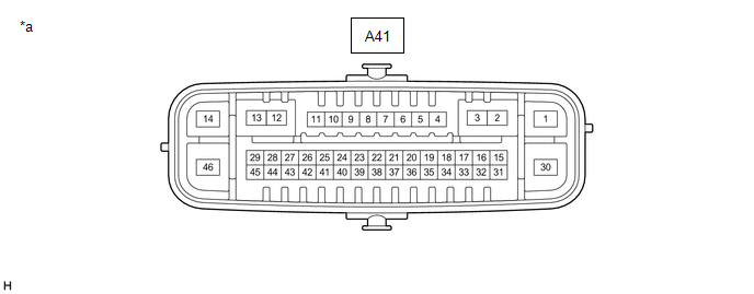
| *a | Component without harness connected (Skid Control ECU (Brake Actuator Assembly)) | - | - |
(a) Disconnect the A41 skid control ECU (brake actuator assembly) connectors.
(b) Measure the voltage and resistance according to the value (s) in the table below.
| Terminal No. (Symbol) | Wiring Color | Terminal Description | Condition | Specified Condition |
|---|---|---|---|---|
| A41-14 (+BS) - Body ground | L - Body ground | Parking brake motor (parking brake actuator assembly) power supply | Always | 11 to 14 V |
| A41-45 (IG1) - Body ground | V - Body ground | IG power supply | Engine switch on (IG) | 11 to 14 V |
| A41-1 (GND1) - Body ground | W-B - Body ground | Ground | Always | Below 1 Ω |
| A41-30 (GND2) - Body ground | W-B - Body ground | Ground | Always | Below 1 Ω |
| A41-13 (MRR+) - Body ground | Y - Body ground | Parking brake motor RH (parking brake actuator assembly RH) (+) | - | - |
| A41-12 (MRR-) - Body ground | R - Body ground | Parking brake motor RH (parking brake actuator assembly RH) (-) | - | - |
| A41-3 (MRL+) - Body ground | B - Body ground | Parking brake motor LH (parking brake actuator assembly LH) (+) | - | - |
| A41-2 (MRL-) - Body ground | L - Body ground | Parking brake motor LH (parking brake actuator assembly LH) (-) | - | - |
| A41-38 (POL) - Body ground | L - Body ground | Electric parking brake switch indicator light | - | - |
| A41-36 (SWI1) - Body ground | G - Body ground | Electric parking brake switch (electric parking brake switch assembly) | - | - |
| A41-31 (SWO1) - Body ground | LG - Body ground | Electric parking brake switch (electric parking brake switch assembly) | - | - |
| A41-41 (SWI2) - Body ground | W - Body ground | Electric parking brake switch (electric parking brake switch assembly) | - | - |
| A41-39 (SWO2) - Body ground | R - Body ground | Electric parking brake switch (electric parking brake switch assembly) | - | - |
| A41-27 (CANH) - Body ground | B - Body ground | CAN communication line H | - | - |
| A41-43 (CANL) - Body ground | W - Body ground | CAN communication line L | - | - |
 Test Mode Procedure
TEST MODE PROCEDURE REAR BRAKE PAD REPLACEMENT MODE *1 Rear Disc Brake Piston *2 Nut *a The nut moves inward in pad replacement mode HINT: When replacing the rear disc brake pad a ...
 Dtc Check / Clear
DTC CHECK / CLEAR CHECK DTC AND FREEZE FRAME DATA (USING TECHSTREAM) (a) Turn the engine switch off. (b) Connect the Techstream to the DLC3. (c) Turn the engine switch on (IG). (d) Turn the Techstream ...
Other materials:
Lexus RX (RX 350L, RX450h) 2016-2026 Owners Manual > Bluetooth Phone: Using a Bluetooth
Phone
The hands-free system is a function that allows you to use your
cellular phone
without touching it.
This system supports Bluetooth. Bluetooth is a wireless data system that
allows the cellular phone to wirelessly connect to the hands-free system and
make/receive calls.
Before making a phone ...
Lexus RX (RX 350L, RX450h) 2016-2026 Repair Manual > Panoramic Moon Roof System: Diagnosis System
DIAGNOSIS SYSTEM DESCRIPTION (a) Panoramic moon roof system data and Diagnostic Trouble Codes (DTCs) can be read through the vehicle Data Link Connector 3 (DLC3). When the system seems to be malfunctioning, use the Techstream to check for malfunctions and perform repairs. CHECK DLC3 (a) Check the DL ...
Lexus RX (RX 350L, RX450h) 2016-{YEAR} Owners Manual
- For your information
- Pictorial index
- For safety and security
- Instrument cluster
- Operation of each component
- Driving
- Lexus Display Audio system
- Interior features
- Maintenance and care
- When trouble arises
- Vehicle specifications
- For owners
Lexus RX (RX 350L, RX450h) 2016-{YEAR} Repair Manual

0.015