Lexus RX (RX 350L, RX450h) 2016-2026 Repair Manual: Electric Parking Brake Switch Signal Compare Failure (C060962)
DESCRIPTION
When the electric parking brake switch is pulled, a lock request signal is sent from the skid control ECU (brake actuator assembly) to the parking brake actuator assembly. When the electric parking brake switch is pushed, a release request signal is sent from the skid control ECU (brake actuator assembly) to the parking brake actuator assembly.
| DTC No. | Detection Item | DTC Detection Condition | Trouble Area | Memory | Note |
|---|---|---|---|---|---|
| C060962 | Electric Parking Brake Switch Signal Compare Failure |
|
| DTC stored | An electric parking brake system malfunction is displayed on the multi-information display. |
| Vehicle Condition | ||||
|---|---|---|---|---|
| Pattern 1 | Pattern 2 | Pattern 3 | ||
| Diagnosis Condition | - | - | - | - |
| Malfunction Status | Parking brake switch open circuit is detected | ○ | - | - |
| Parking brake switch short circuit is detected | - | ○ | - | |
| Parking brake switch stuck malfunction | - | - | ○ | |
| Detection Time | 1 second or more | 1 second or more | - | |
| Number of Trips | 1 trip | 1 trip | 1 trip | |
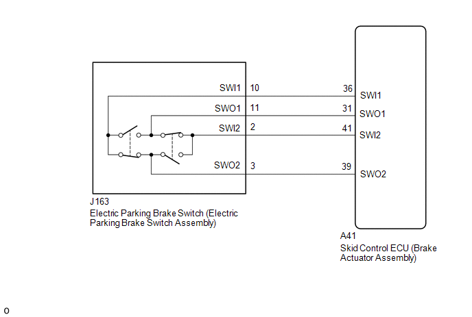
WIRING DIAGRAM
CAUTION / NOTICE / HINT
NOTICE:
- If the electric parking brake switch is held near the lock position but not fully in the lock position for 1 second or more, a DTC may be stored due to one of the two contacts being ON while the other is OFF. (This is not a system malfunction.)
- The electric parking brake may still operate up to 20 seconds after the engine switch is turned off. Before disconnecting connectors or fuses, turn the engine switch off and wait 20 seconds or more.
-
After replacing the skid control ECU (brake actuator assembly), perform "Calibration".
Click here
.gif)
- When replacing the skid control ECU (brake actuator assembly), operate the electric parking brake switch (electric parking brake switch assembly) as the parking brake indicator light (red) blinks when the engine switch is first turned on (IG).
PROCEDURE
| 1. | INSPECT ELECTRIC PARKING BRAKE SWITCH (ELECTRIC PARKING BRAKE SWITCH ASSEMBLY) |
(a) Remove the electric parking brake switch (electric parking brake switch assembly).
Click here
(b) Inspect the electric parking brake switch (electric parking brake switch assembly).
Click here
| NG | .gif) | REPLACE ELECTRIC PARKING BRAKE SWITCH (ELECTRIC PARKING BRAKE SWITCH ASSEMBLY) |
|
.gif)
| 2. | CHECK HARNESS AND CONNECTOR (SKID CONTROL ECU (BRAKE ACTUATOR ASSEMBLY) - ELECTRIC PARKING BRAKE SWITCH (ELECTRIC PARKING BRAKE SWITCH ASSEMBLY)) |
(a) Disconnect the J163 electric parking brake switch (electric parking brake switch assembly) connector.
(b) Disconnect the A41 skid control ECU (brake actuator assembly) connector.
(c) Measure the resistance according to the value(s) in the table below.
Standard Resistance:
| Tester Connection | Condition | Specified Condition |
|---|---|---|
| A41-36 (SWI1) - J163-10 (SWI1) | Always | Below 1 Ω |
| A41-31 (SWO1) - J163-11 (SWO1) | Always | Below 1 Ω |
| A41-41 (SWI2) - J163-2 (SWI2) | Always | Below 1 Ω |
| A41-39 (SWO2) - J163-3 (SWO2) | Always | Below 1 Ω |
| A41-36 (SWI1) or J163-10 (SWI1) - Body ground | Always | 10 kΩ or higher |
| A41-31 (SWO1) or J163-11 (SWO1) - Body ground | Always | 10 kΩ or higher |
| A41-41 (SWI2) or J163-2 (SWI2) - Body ground | Always | 10 kΩ or higher |
| A41-39 (SWO2) or J163-3 (SWO2) - Body ground | Always | 10 kΩ or higher |
| NG | | REPAIR OR REPLACE HARNESS OR CONNECTOR |
|
| 3. | CLEAR DTC |
(a) Clear the DTCs.
Chassis > Brake/EPB > Clear DTCs(b) Turn the engine switch off.
|
| 4. | CHECK DTC |
(a) Check for DTCs.
Chassis > Brake/EPB > Trouble Codes| Result | Proceed to |
|---|---|
| DTCs are output | A |
| DTCs are not output | B |
| A | | REPLACE SKID CONTROL ECU (BRAKE ACTUATOR ASSEMBLY) |
| B | | USE SIMULATION METHOD TO CHECK |
 Vehicle Control History
VEHICLE CONTROL HISTORY DESCRIPTION
Vehicle Control History is a function that captures and stores ECU data when triggered by specific vehicle behavior.
If the customer states that the engine sta ...
 Left Electric Parking Brake Actuator Control Circuit Short to Ground (C060B11)
DESCRIPTION DTC No. Detection Item DTC Detection Condition Trouble Area Memory Note C060B11 Left Electric Parking Brake Actuator Control Circuit Short to Ground
Diagnosis Condi ...
Other materials:
Lexus RX (RX 350L, RX450h) 2016-2026 Repair Manual > Power Tilt And Power Telescopic Steering Column System: Terminals Of Ecu
TERMINALS OF ECU MULTIPLEX TILT AND TELESCOPIC ECU *a Component without harness connected (Multiplex Tilt and Telescopic ECU) - - (a) Measure the voltage and resistance according to the value(s) in the table below. Terminal No. (Symbol) Wiring Color Terminal Description Conditi ...
Lexus RX (RX 350L, RX450h) 2016-2026 Repair Manual > Intuitive Parking Assist System (w/ Intelligent Clearance Sonar System): Front Right Center Sensor (C1AE3)
DESCRIPTION The front center ultrasonic sensor RH is installed to the front bumper. The clearance warning ECU assembly detects obstacles based on signals received from the front center ultrasonic sensor RH. If the front center ultrasonic sensor RH has an open circuit or other malfunction, it will no ...
Lexus RX (RX 350L, RX450h) 2016-{YEAR} Owners Manual
- For your information
- Pictorial index
- For safety and security
- Instrument cluster
- Operation of each component
- Driving
- Lexus Display Audio system
- Interior features
- Maintenance and care
- When trouble arises
- Vehicle specifications
- For owners
Lexus RX (RX 350L, RX450h) 2016-{YEAR} Repair Manual

0.0157