Lexus RX (RX 350L, RX450h) 2016-2026 Repair Manual: Disassembly
DISASSEMBLY
PROCEDURE
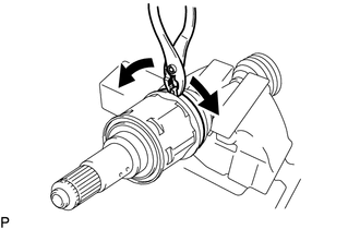
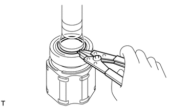
1. SEPARATE FRONT NO. 2 AXLE INBOARD JOINT BOOT CLAMP
(a) Secure the drive shaft in a vise between aluminum plates.
NOTICE:
Do not overtighten the vise.
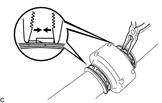
| (b) Using pliers, separate the front No. 2 axle inboard joint boot clamp. |
|
2. SEPARATE FRONT AXLE INBOARD JOINT BOOT CLAMP
HINT:
Perform the same procedure as for the front No. 2 axle inboard joint boot clamp.
3. SEPARATE FRONT AXLE INBOARD JOINT BOOT
(a) Separate the front axle inboard joint boot from the front drive inboard joint assembly.
4. REMOVE FRONT DRIVE INBOARD JOINT ASSEMBLY (for TMC Made)
(a) Remove the old grease from the front drive inboard joint assembly.
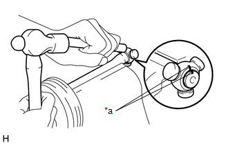
| (b) Put matchmarks on the front drive inboard joint assembly and front drive outboard joint shaft assembly. NOTICE: Do not use a punch for the marks. |
|
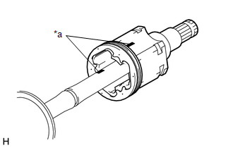
(c) Remove the front drive inboard joint assembly from the front drive outboard joint shaft assembly.
(d) Secure the drive shaft in a vise between aluminum plates.
NOTICE:
Do not overtighten the vise.
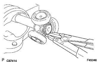
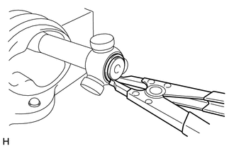
| (e) Using a snap ring expander, remove the shaft snap ring from the front drive outboard joint shaft assembly. |
|
| (f) Put matchmarks on the front drive outboard joint shaft assembly and tripod joint. NOTICE: Do not use a punch for the marks. |
|
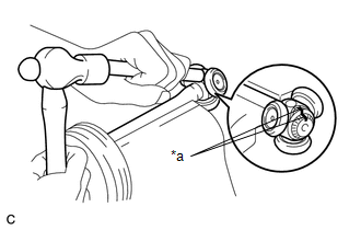
(g) Using a brass bar and a hammer, tap out the tripod joint from the front drive outboard joint shaft assembly.
NOTICE:
- Do not tap the rollers.
- Do not drop the tripod joint.
| (h) Remove the front axle inboard joint grommet from the front drive inboard joint assembly. |
|
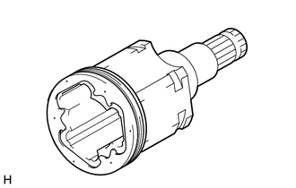
5. REMOVE FRONT DRIVE INBOARD JOINT ASSEMBLY (for TMMC Made)
(a) Remove the old grease from the front drive inboard joint assembly.
| (b) Put matchmarks on the front drive inboard joint assembly and front drive outboard joint shaft assembly. NOTICE: Do not use a punch for the marks. |
|
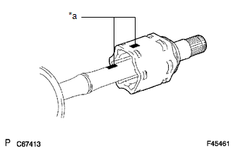
(c) Remove the front drive inboard joint assembly from the front drive outboard joint shaft assembly.
NOTICE:
- Be careful when removing the front drive inboard joint assembly from the front drive outboard joint shaft assembly as the rollers of the tripod joint may fall out.
- Do not drop the rollers of the tripod joint.
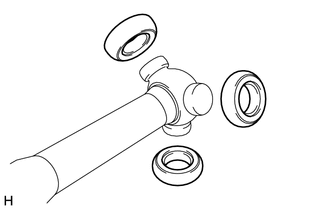
| (d) Remove the 3 rollers from the tripod joint. |
|
(e) Secure the drive shaft in a vise between aluminum plates.
NOTICE:
Do not overtighten the vise.
| (f) Using a snap ring expander, remove the shaft snap ring from the front drive outboard joint shaft assembly. |
|
| (g) Put matchmarks on the front drive outboard joint shaft assembly and tripod joint. NOTICE: Do not use a punch for the marks. |
|
(h) Using a brass bar and a hammer, tap out the tripod joint from the front drive outboard joint shaft assembly.
NOTICE:
- Do not tap the areas where the rollers contact the tripod joint.
- Do not drop the tripod joint.
6. REMOVE FRONT AXLE INBOARD JOINT BOOT
(a) Remove the front No. 2 axle inboard joint boot clamp, front axle inboard joint boot and front axle inboard joint boot clamp.
7. REMOVE FRONT DRIVE SHAFT DAMPER CLAMP (w/ Drive Shaft Damper)
| (a) Using needle-nose pliers, separate the 2 front drive shaft damper clamps. |
|
8. REMOVE FRONT DRIVE SHAFT DAMPER (w/ Drive Shaft Damper)
(a) Remove the front drive shaft damper and 2 front drive shaft damper clamps from the front drive outboard joint shaft assembly.
9. SEPARATE FRONT NO. 2 AXLE OUTBOARD JOINT BOOT CLAMP (for LH Side)
NOTICE:
Do not disassemble the outboard joint shaft assembly for RH side.
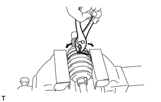
| (a) Using pliers, separate the front No. 2 axle outboard joint boot clamp. |
|
10. SEPARATE FRONT AXLE OUTBOARD JOINT BOOT CLAMP (for LH Side)
NOTICE:
Do not disassemble the outboard joint shaft assembly for RH side.
HINT:
Perform the same procedure as for the front No. 2 axle outboard joint boot clamp.
11. REMOVE FRONT AXLE OUTBOARD JOINT BOOT (for LH Side)
NOTICE:
Do not disassemble the outboard joint shaft assembly for RH side.
(a) Remove the front axle outboard joint boot clamp, front axle outboard joint boot and front No. 2 axle outboard joint boot clamp from the front drive outboard joint shaft assembly.
(b) Remove the old grease from the outboard joint.
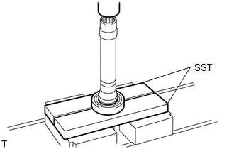
12. REMOVE FRONT DRIVE SHAFT DUST COVER LH
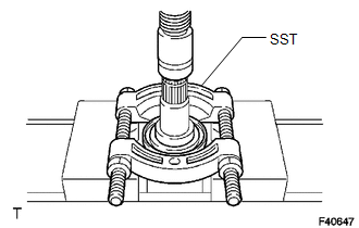
| (a) Using SST and a press, remove the front drive shaft dust cover LH. SST: 09950-00020 NOTICE:
|
|
13. REMOVE FRONT DRIVE SHAFT DUST COVER RH (for 2WD RH Side)
HINT:
Perform the same procedure as for the LH side.
14. REMOVE FRONT DRIVE SHAFT BEARING (for RH Side)
| (a) Using a snap ring expander, remove the drive shaft hole snap ring. |
|
| (b) Using SST and a press, remove the front drive shaft bearing. SST: 09527-10011 NOTICE: Do not drop the front drive inboard joint assembly. |
|
 Inspection
INSPECTION PROCEDURE 1. INSPECT FRONT DRIVE SHAFT ASSEMBLY (a) Check that there is no excessive play in the radial direction of the outboard joint. (b) Check that the inboard joint slid ...
 Reassembly
REASSEMBLY PROCEDURE 1. INSTALL FRONT DRIVE SHAFT BEARING (for RH Side) (a) Using SST, a steel plate and a press, install a new front drive shaft bearing. SST: 09527-10011 NOTICE: The bearing shoul ...
Other materials:
Lexus RX (RX 350L, RX450h) 2016-2026 Repair Manual > Hazard Warning Switch: Removal
REMOVAL CAUTION / NOTICE / HINT The necessary procedures (adjustment, calibration, initialization or registration) that must be performed after parts are removed and installed, or replaced during hazard warning switch (radio receiver assembly)removal/installation are shown below. Necessary Procedure ...
Lexus RX (RX 350L, RX450h) 2016-2026 Repair Manual > Millimeter Wave Radar Sensor: Removal
REMOVAL CAUTION / NOTICE / HINT The necessary procedures (adjustment, calibration, initialization, or registration) that must be performed after parts are replaced during millimeter wave radar sensor assembly removal/installation are shown below. Necessary Procedure After Parts Removed/Installed/Rep ...
Lexus RX (RX 350L, RX450h) 2016-{YEAR} Owners Manual
- For your information
- Pictorial index
- For safety and security
- Instrument cluster
- Operation of each component
- Driving
- Lexus Display Audio system
- Interior features
- Maintenance and care
- When trouble arises
- Vehicle specifications
- For owners
Lexus RX (RX 350L, RX450h) 2016-{YEAR} Repair Manual

0.0139