Lexus RX (RX 350L, RX450h) 2016-2026 Repair Manual: Reassembly
REASSEMBLY
PROCEDURE
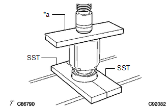
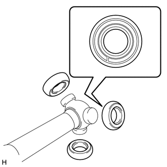
1. INSTALL FRONT DRIVE SHAFT BEARING (for RH Side)
| (a) Using SST, a steel plate and a press, install a new front drive shaft bearing. SST: 09527-10011 NOTICE: The bearing should be completely installed. |
|
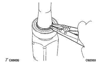
| (b) Using a snap ring expander, install a new drive shaft hole snap ring. NOTICE: Install the drive shaft hole snap ring securely. |
|
2. INSTALL FRONT DRIVE SHAFT DUST COVER LH
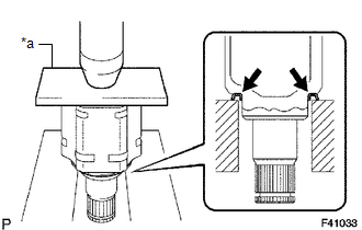
| (a) Using a steel plate and a press, install a new front drive shaft dust cover LH. NOTICE:
|
|
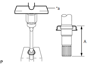
3. INSTALL FRONT DRIVE SHAFT DUST COVER RH (for 2WD RH Side)
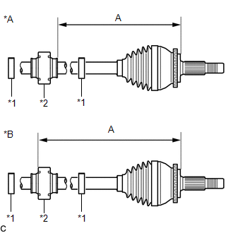
| (a) Using a steel plate and a press, install a new front drive shaft dust cover RH until the dimension (A) from the tip of the front drive inboard joint assembly to the front drive shaft dust cover RH meets the specification. Dimension (A): 115.5 to 116.5 mm (4.55 to 4.58 in.) NOTICE: Be careful not to damage the front drive shaft dust cover RH. |
|
4. INSTALL FRONT AXLE OUTBOARD JOINT BOOT (for LH Side)
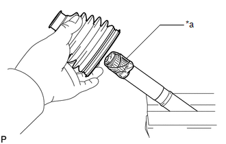
| (a) Wrap the splines of the front drive outboard joint shaft assembly with protective tape to prevent the boot from being damaged. |
|
(b) Install new parts to the front drive outboard joint shaft assembly in the following order:
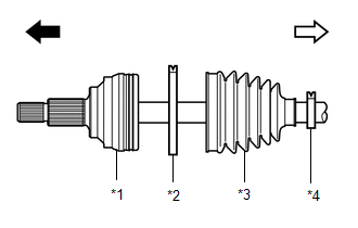
| *1 | Front Drive Outboard Joint Shaft Assembly |
| *2 | Front No. 2 Axle Outboard Joint Boot Clamp |
| *3 | Front Axle Outboard Joint Boot |
| *4 | Front Axle Outboard Joint Boot Clamp |
.png) | Outboard Joint Side |
.png) | Inboard Joint Side |
(1) Front No. 2 axle outboard joint boot clamp
(2) Front axle outboard joint boot
(3) Front axle outboard joint boot clamp
(c) Pack the joint portion of the front drive outboard joint shaft assembly and front axle outboard joint boot with grease.
Standard Grease Capacity:
for TMC Made
81 to 91 g (2.86 to 3.20 oz)
for TMMC Made
137 to 147 g (4.84 to 5.18 oz)
(d) Install the front axle outboard joint boot to the front drive outboard joint shaft assembly groove.
NOTICE:
- Do not allow grease to adhere to the boot clamp track of the outboard joint boot.
- Keep the inside of the outboard joint boot free of foreign matter.
5. INSTALL FRONT AXLE OUTBOARD JOINT BOOT CLAMP (for LH Side)
(a) Secure the drive shaft in a vise between aluminum plates.
NOTICE:
Do not overtighten the vise.
(b) Install the front axle outboard joint boot clamp to the front axle outboard joint boot.
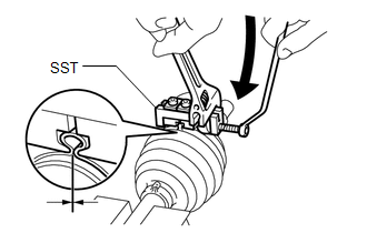
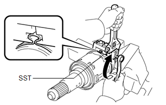
| (c) Place SST onto the front axle outboard joint boot clamp, press it against the boot and slightly tighten SST. SST: 09521-24010 |
|
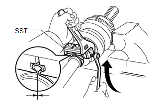
(d) Tighten SST so that the front axle outboard joint boot clamp is pinched.
NOTICE:
Do not overtighten SST.
(e) Remove SST.
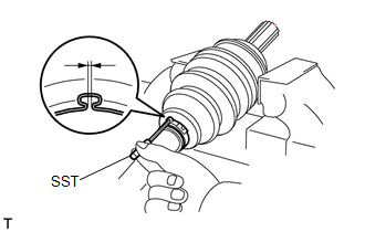
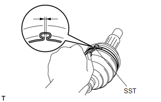
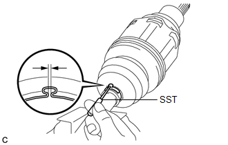
| (f) Using SST, measure the clearance of the front axle outboard joint boot clamp. SST: 09240-00020 Clearance: for TMC Made 0.5 to 1.5 mm (0.0197 to 0.0590 in.) for TMMC Made 1.3 mm (0.0511 in.) or less If the clearance is not as specified, retighten SST. |
|
6. INSTALL FRONT NO. 2 AXLE OUTBOARD JOINT BOOT CLAMP (for LH Side)
(a) Secure the drive shaft in a vise between aluminum plates.
NOTICE:
Do not overtighten the vise.
(b) Install the front No. 2 axle outboard joint boot clamp to the front axle outboard joint boot.
| (c) Place SST onto the front No. 2 axle outboard joint boot clamp, press it against the boot and slightly tighten SST. SST: 09521-24010 |
|
(d) Tighten SST so that the front No. 2 axle outboard joint boot clamp is pinched.
NOTICE:
Do not overtighten SST.
(e) Remove SST.
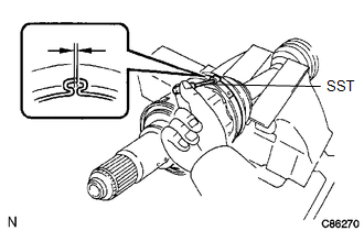
| (f) Using SST, measure the clearance of the front No. 2 axle outboard joint boot clamp. SST: 09240-00020 Clearance: for TMC Made 0.5 to 1.5 mm (0.0197 to 0.0590 in.) for TMMC Made 2.1 mm (0.0826 in.) or less If the clearance is not as specified, retighten SST. |
|
7. INSTALL FRONT DRIVE SHAFT DAMPER (w/ Drive Shaft Damper)
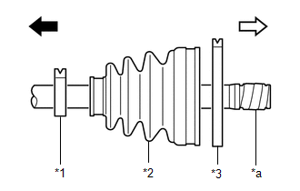
| (a) Temporarily install the front drive shaft damper and 2 new front drive shaft damper clamps to the front drive outboard joint shaft assembly as shown in the illustration. |
|
(b) Set the dimension (A) as specified below.
Dimension (A) for TMC Made:
| for LH Side | 235.0 to 239.0 mm (9.26 to 9.40 in.) |
| for RH Side | 240.0 to 244.0 mm (9.45 to 9.60 in.) |
Dimension (A) for TMMC Made:
| for LH Side | 288.0 to 292.0 mm (11.34 to 11.49 in.) |
| for RH Side | 276.0 to 280.0 mm (10.87 to 11.02 in.) |
(c) Install the 2 front drive shaft damper clamps to the front drive shaft damper.
NOTICE:
Make sure to install the clamps in the correct position.
8. INSTALL FRONT DRIVE SHAFT DAMPER CLAMP (w/ Drive Shaft Damper)
| (a) Using needle-nose pliers, install the 2 front drive shaft damper clamps. |
|
.png)
9. INSTALL FRONT DRIVE INBOARD JOINT ASSEMBLY (for TMC Made)
(a) Install new parts to the front drive outboard joint shaft assembly in the following order:
| *1 | Front Axle Inboard Joint Boot Clamp |
| *2 | Front Axle Inboard Joint Boot |
| *3 | Front No. 2 Axle Inboard Joint Boot Clamp |
| *a | Protective Tape |
| | Outboard Joint Side |
| | Inboard Joint Side |
(1) Front axle inboard joint boot clamp
(2) Front axle inboard joint boot
(3) Front No. 2 axle inboard joint boot clamp
(b) Secure the drive shaft in a vise between aluminum plates.
NOTICE:
Do not overtighten the vise.
(c) Remove the protective tape.
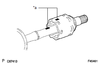
| (d) Align the matchmarks and install the tripod joint to the front drive outboard joint shaft assembly. NOTICE: Face the serrated side of the tripod joint outward and install it to the outboard joint end. |
|
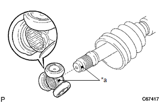
(e) Using a brass bar and a hammer, install the tripod joint to the front drive outboard joint shaft assembly.
NOTICE:
- Do not tap the rollers.
- Keep the tripod joint free of foreign matter.
- Make sure to install the tripod joint in the correct direction.
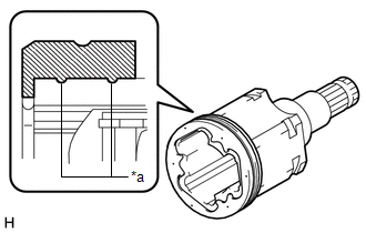
| (f) Using a snap ring expander, install a new shaft snap ring to the front drive outboard joint shaft assembly. |
|
.png)
(g) Pack the front drive inboard joint assembly and front axle inboard joint boot with grease.
Standard Grease Capacity:
190 to 200 g (6.71 to 7.05 oz)
| (h) Install a new front axle inboard joint grommet to the front drive inboard joint assembly. NOTICE:
|
|
| (i) Align the matchmarks and install the front drive inboard joint assembly to the front drive outboard joint shaft assembly. |
|
10. INSTALL FRONT DRIVE INBOARD JOINT ASSEMBLY (for TMMC Made)
(a) Install new parts to the front drive outboard joint shaft assembly in the following order:
| *1 | Front Axle Inboard Joint Boot Clamp |
| *2 | Front Axle Inboard Joint Boot |
| *3 | Front No. 2 Axle Inboard Joint Boot Clamp |
| *a | Protective Tape |
| | Outboard Joint Side |
| | Inboard Joint Side |
(1) Front axle inboard joint boot clamp
(2) Front axle inboard joint boot
(3) Front No. 2 axle inboard joint boot clamp
(b) Secure the drive shaft in a vise between aluminum plates.
NOTICE:
Do not overtighten the vise.
(c) Remove the protective tape.
| (d) Align the matchmarks and install the tripod joint to the front drive outboard joint shaft assembly. NOTICE: Face the serrated side of the tripod joint outward and install it to the outboard joint end. |
|
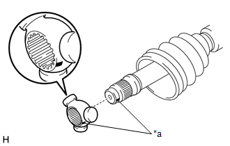
(e) Using a brass bar and a hammer, install the tripod joint to the front drive outboard joint shaft assembly.
NOTICE:
- Do not tap the areas where the rollers contact the tripod joint.
- Keep the tripod joint free of foreign matter.
- Make sure to install the tripod joint in the correct direction.
| (f) Using a snap ring expander, install a new shaft snap ring to the front drive outboard joint shaft assembly. |
|
.png)
(g) Pack the front drive inboard joint assembly and front axle inboard join boot with grease.
Standard Grease Capacity:
189 to 199 g (6.67 to 7.01 oz)
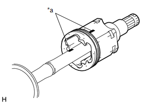
| (h) Install the 3 rollers to the tripod joint. NOTICE:
|
|
| (i) Align the matchmarks and install the front drive inboard joint assembly to the front drive outboard joint shaft assembly. |
|
11. INSTALL FRONT AXLE INBOARD JOINT BOOT
(a) Install the front axle inboard joint boot to the front drive inboard joint assembly.
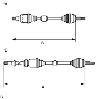
| (b) Check whether the dimension (A) of each drive shaft is within specification. Dimension (A) for TMC Made:
Dimension (A) for TMMC Made:
|
|
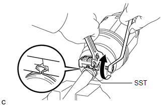
12. INSTALL FRONT AXLE INBOARD JOINT BOOT CLAMP
(a) Secure the drive shaft in a vise between aluminum plates.
NOTICE:
Do not overtighten the vise.
(b) Install the front axle inboard joint boot clamp to the front axle inboard joint boot.
| (c) Place SST onto the front axle inboard joint boot clamp, press it against the boot and slightly tighten SST. SST: 09521-24010 |
|
(d) Tighten SST so that the front axle inboard joint boot clamp is pinched.
NOTICE:
Do not overtighten SST.
(e) Remove SST.
| (f) Using SST, measure the clearance of the front axle inboard joint boot clamp. SST: 09240-00020 Clearance: for TMC Made 0.5 to 1.5 mm (0.0197 to 0.0590 in.) for TMMC Made 1.3 mm (0.0511 in.) or less If the clearance is not as specified, retighten SST. |
|
13. INSTALL FRONT NO. 2 AXLE INBOARD JOINT BOOT CLAMP
(a) Secure the drive shaft in a vise between aluminum plates.
NOTICE:
Do not overtighten the vise.
(b) Install the front No. 2 axle inboard joint boot clamp to the front axle inboard joint boot.
| (c) Place SST onto the front No. 2 axle inboard joint boot clamp, press it against the boot and slightly tighten SST. SST: 09521-24010 |
|
(d) Tighten SST so that the front No. 2 axle inboard joint boot clamp is pinched.
NOTICE:
Do not overtighten SST.
(e) Remove SST.
| (f) Using SST, measure the clearance of the front No. 2 axle inboard joint boot clamp. SST: 09240-00020 Clearance: for TMC Made 0.5 to 1.5 mm (0.0197 to 0.0590 in.) for TMMC Made 2.1 mm (0.0826 in.) or less If the clearance is not as specified, retighten SST. |
|
14. INSPECT FRONT DRIVE SHAFT ASSEMBLY
Click here .gif)
 Disassembly
DISASSEMBLY PROCEDURE 1. SEPARATE FRONT NO. 2 AXLE INBOARD JOINT BOOT CLAMP (a) Secure the drive shaft in a vise between aluminum plates. NOTICE: Do not overtighten the vise. (b) Using pliers, sepa ...
 Installation
INSTALLATION CAUTION / NOTICE / HINT HINT:
Use the same procedure for the RH side and LH side.
The following procedure is for the LH side.
PROCEDURE 1. INSTALL FRONT DRIVE SHAFT HOLE SNAP RING ...
Other materials:
Lexus RX (RX 350L, RX450h) 2016-2026 Repair Manual > Lighting System (w/o Automatic Headlight Beam Level Control System): Dtc Check / Clear
DTC CHECK / CLEAR CHECK FOR DTC (MAIN BODY) (a) Connect the Techstream to the DLC3. (b) Turn the engine switch on (IG). (c) Turn the Techstream on. (d) Enter the following menus: Body Electrical / Main Body / Trouble Codes. Body Electrical > Main Body > Trouble Codes (e) Check for DTCs. CHECK ...
Lexus RX (RX 350L, RX450h) 2016-2026 Repair Manual > Fuel Pressure Sensor: Inspection
INSPECTION PROCEDURE 1. INSPECT FUEL DELIVERY PIPE SUB-ASSEMBLY (FUEL PRESSURE SENSOR) NOTICE:
Do not remove the fuel pressure sensor from the fuel delivery pipe sub-assembly.
If the fuel pressure sensor is removed, replace the fuel delivery pipe sub-assembly (fuel pressure sensor) with a new o ...
Lexus RX (RX 350L, RX450h) 2016-{YEAR} Owners Manual
- For your information
- Pictorial index
- For safety and security
- Instrument cluster
- Operation of each component
- Driving
- Lexus Display Audio system
- Interior features
- Maintenance and care
- When trouble arises
- Vehicle specifications
- For owners
Lexus RX (RX 350L, RX450h) 2016-{YEAR} Repair Manual

0.0124