Lexus RX (RX 350L, RX450h) 2016-2026 Repair Manual: Installation
INSTALLATION
CAUTION / NOTICE / HINT
HINT:
- Use the same procedure for the RH side and LH side.
- The following procedure is for the LH side.
PROCEDURE
1. INSTALL FRONT DRIVE SHAFT HOLE SNAP RING (for LH Side)
(a) Install a new front drive shaft hole snap ring.
NOTICE:
Face the end gap of the front drive shaft hole snap ring downward.
2. INSTALL FRONT DRIVE SHAFT ASSEMBLY LH
(a) Coat the splines of the front drive inboard joint assembly with ATF WS.
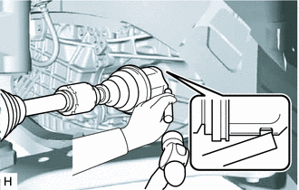
| (b) Align the inboard joint splines, and using a brass bar and a hammer, install the front drive shaft assembly LH. NOTICE:
HINT: Confirm whether the drive shaft is securely driven in by checking the reaction force and sound. |
|
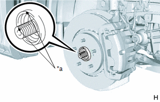
(c) Apply 0.1 to 0.3 g (0.00353 to 0.0105 oz) of Toyota Body Grease W to each of the 4 areas shown in the illustration.
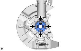
.png) | Toyota Body Grease W |
| (d) Align the matchmarks and install the front drive shaft assembly LH to the front axle hub sub-assembly. NOTICE:
|
|
3. INSTALL FRONT DRIVE SHAFT ASSEMBLY RH (for 2WD)
(a) Install a new bearing bracket hole snap ring to the front drive shaft assembly RH.
(b) Coat the splines of the front drive inboard joint assembly with ATF WS.
(c) Align the inboard joint splines, and securely insert the front drive shaft assembly RH.
NOTICE:
- Do not damage the front drive shaft oil seal RH.
- Do not damage the front axle inboard joint boot.
- When inserting the front drive shaft assembly RH, keep it level.
| (d) Install the bearing bracket hole snap ring and a new No. 1 drive shaft bearing bracket setting bolt. Torque: 32.4 N·m {330 kgf·cm, 24 ft·lbf} |
|
.png)
(e) Apply 0.1 to 0.3 g (0.00353 to 0.0105 oz) of Toyota Body Grease W to each of the 4 areas shown in the illustration.
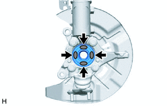
| | Toyota Body Grease W |
| (f) Align the matchmarks and install the front drive shaft assembly RH to the front axle hub sub-assembly. NOTICE:
|
|
4. INSTALL FRONT DRIVE SHAFT ASSEMBLY RH (for AWD)
(a) Install a new bearing bracket hole snap ring to the front drive shaft assembly RH.
(b) Coat the splines of the front drive inboard joint assembly with Toyota genuine differential gear oil LT.
(c) Align the inboard joint splines, and securely insert the front drive shaft assembly RH.
NOTICE:
- Do not damage the transfer case oil seal RH.
- Do not damage the front axle inboard joint boot.
- When inserting the front drive shaft assembly RH, keep it level.
| (d) Install the bearing bracket hole snap ring and a new No. 1 drive shaft bearing bracket setting bolt. Torque: 32.4 N·m {330 kgf·cm, 24 ft·lbf} |
|
.png)
(e) Apply 0.1 to 0.3 g (0.00353 to 0.0105 oz) of Toyota Body Grease W to each of the 4 areas shown in the illustration.
| | Toyota Body Grease W |
| (f) Align the matchmarks and install the front drive shaft assembly RH to the front axle hub sub-assembly. NOTICE:
|
|
5. CONNECT FRONT LOWER NO. 1 SUSPENSION ARM SUB-ASSEMBLY
Click here .gif)
6. INSTALL FRONT STABILIZER LINK ASSEMBLY
Click here
7. CONNECT TIE ROD ASSEMBLY
Click here
8. INSTALL FRONT SPEED SENSOR (w/o AVS)
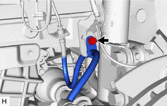
| (a) Install the front speed sensor to the steering knuckle with the bolt. Torque: 8.5 N·m {87 kgf·cm, 75 in·lbf} NOTICE:
|
|
.png)
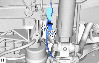
(b) Engage the 2 claws to install the sensor clamp.
NOTICE:
Do not twist the front speed sensor wire harness when installing it.
| (c) Engage the 2 claws to install the sensor clamp. NOTICE: Do not twist the front speed sensor wire harness when installing it. |
|
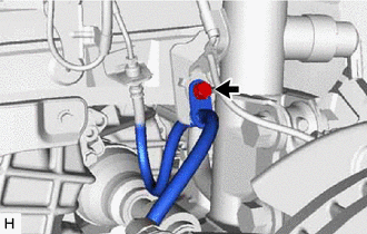
| (d) Install the front flexible hose with the bolt. Torque: 18.8 N·m {192 kgf·cm, 14 ft·lbf} |
|
9. INSTALL FRONT SPEED SENSOR (w/ AVS)
| (a) Install the front speed sensor to the steering knuckle with the bolt. Torque: 8.5 N·m {87 kgf·cm, 75 in·lbf} NOTICE:
|
|
.png)
| (b) Install the front skid control sensor wire to the front shock absorber assembly with the bolt. Torque: 10 N·m {102 kgf·cm, 7 ft·lbf} |
|
.png)
(c) Connect the connector to the front shock absorber assembly.
NOTICE:
Do not twist the front skid control sensor wire harness when installing it.
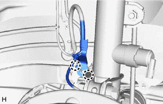
| (d) Engage the 2 claws to install the sensor clamp. NOTICE: Do not twist the front skid control sensor wire harness when installing it. |
|
| (e) Install the front flexible hose with the bolt. Torque: 18.8 N·m {192 kgf·cm, 14 ft·lbf} |
|
10. INSTALL FRONT AXLE SHAFT NUT
(a) Clean the threaded parts on the front drive shaft assembly and a new front axle shaft nut using non-residue solvent.
NOTICE:
- Make sure to perform this work even when using a new front drive shaft assembly.
- Keep the threaded parts free of oil and foreign matter.
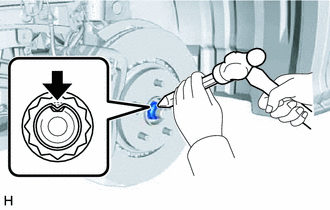
(b) Using a 30 mm deep socket wrench, install the front axle shaft nut.
Torque:
294 N·m {2998 kgf·cm, 217 ft·lbf}
HINT:
Depress the brake pedal to prevent the drive shaft from rotating.
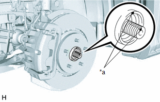
| (c) Using a chisel and hammer, stake the front axle shaft nut. |
|
11. ADD TRANSFER OIL (for AWD)
Click here
12. ADD AUTOMATIC TRANSAXLE FLUID
for U881E:
Click here
for U881F:
Click here
13. INSPECT TRANSFER OIL LEAK (for AWD)
14. INSTALL FRONT FENDER APRON SEAL LH
Click here
15. INSTALL NO. 3 ENGINE UNDER COVER
Click here
16. INSTALL FRONT WHEEL OPENING EXTENSION PAD LH
Click here
17. INSTALL FRONT WHEELS
Click here
18. INSPECT AND ADJUST FRONT WHEEL ALIGNMENT
Click here
19. CHECK FOR SPEED SENSOR SIGNAL
Click here
 Reassembly
REASSEMBLY PROCEDURE 1. INSTALL FRONT DRIVE SHAFT BEARING (for RH Side) (a) Using SST, a steel plate and a press, install a new front drive shaft bearing. SST: 09527-10011 NOTICE: The bearing shoul ...

Other materials:
Lexus RX (RX 350L, RX450h) 2016-2026 Repair Manual > Blind Spot Monitor Sensor: Components
COMPONENTS ILLUSTRATION *1 BLIND SPOT MONITOR SENSOR LH *2 BLIND SPOT MONITOR SENSOR RH N*m (kgf*cm, ft.*lbf): Specified torque - - ...
Lexus RX (RX 350L, RX450h) 2016-2026 Repair Manual > Sfi System: VIN Not Programmed (P063051)
MONITOR DESCRIPTION DTC P063051 is stored when the Vehicle Identification Number (VIN) is not stored in the ECM or the stored VIN is not accurate. DTC No. Detection Item DTC Detection Condition Trouble Area MIL Memory Note P063051 VIN Not Programmed Either of the following con ...
Lexus RX (RX 350L, RX450h) 2016-{YEAR} Owners Manual
- For your information
- Pictorial index
- For safety and security
- Instrument cluster
- Operation of each component
- Driving
- Lexus Display Audio system
- Interior features
- Maintenance and care
- When trouble arises
- Vehicle specifications
- For owners
Lexus RX (RX 350L, RX450h) 2016-{YEAR} Repair Manual

0.0146