Lexus RX (RX 350L, RX450h) 2016-2026 Repair Manual: Removal
REMOVAL
CAUTION / NOTICE / HINT
The necessary procedures (adjustment, calibration, initialization or registration) that must be performed after parts are removed and installed, or replaced during transfer assembly removal/installation are shown below.
Necessary Procedure After Parts Removed/Installed/Replaced| Replacement Part or Performed Procedure | Necessary Procedure | Effect/Inoperative Function when Necessary Procedure not Performed | Link |
|---|---|---|---|
| Battery terminal is disconnected/reconnected | Memorize steering angle neutral point | Lane Control System | |
| Pre-collision system | |||
| Intelligent clearance sonar system*1 | |||
| Lighting system (w/ Automatic Headlight Beam Level Control System) | | ||
| Parking assist monitor system | | ||
| Panoramic view monitor system | | ||
| Initialize back door lock | Power door lock control system | | |
| Reset back door close position | Power Back Door System (w/ Outside Door Control Switch) | | |
| Replacement of automatic transaxle assembly | Perform the following procedures in the order shown:
|
| for Initialization: for Registration: |
| Replacement of ECM (If possible, read the transaxle compensation code from the previous ECM) | Perform the following procedures in the order shown:
| ||
| Replacement of ECM (If impossible, read the transaxle compensation code from the previous ECM) | Perform the following procedures in the order shown:
| ||
| Front wheel alignment adjustment | Calibration |
| |
| Suspension, tires, etc. (The vehicle height changes because of suspension or tire replacement) |
|
| |
| Rear television camera assembly optical axis (Back camera position setting) | Parking assist monitor system | for Initialization: for Calibration: | |
| Panoramic view monitor system | for Initialization: for Calibration: | |
| Initialize No. 1 headlight ECU sub-assembly LH | Lighting System (w/ Automatic Headlight Beam Level Control System) | | |
| Replacement of throttle body with motor assembly | Inspection After Repair |
| |
| Cleaning the deposits from the throttle body with motor assembly | |||
| Air leaks from intake system is repaired | |||
| Gas leak from exhaust system is repaired | |||
| Replacement of ECM | Vehicle Identification Number (VIN) registration | MIL comes on | |
| ECU communication ID registration (Immobiliser system) | Engine start function | | |
| Perform code registration (Immobiliser system) |
| |
*1: When performing learning using the Techstream.
Click here .gif)
CAUTION:
The automatic transaxle assembly is very heavy. Be sure to follow the procedure described in the repair manual, or the transmission jack may suddenly drop.
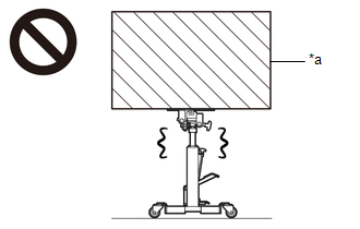
| *a | Object Exceeding Weight Limit of Transmission Jack |
NOTICE:
If automatic transaxle parts are replaced, refer to Parts Replacement Compensation Table to determine if any additional operations are necessary.
Click here
PROCEDURE
1. REMOVE AUTOMATIC TRANSAXLE ASSEMBLY
Click here
2. REMOVE TRANSFER ASSEMBLY
| (a) Remove the 8 nuts. |
|
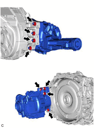
(b) Using a plastic hammer, remove the transfer assembly from the automatic transaxle assembly.
NOTICE:
- Remove the transfer assembly from the automatic transaxle assembly without tilting it.
- During removal, do not hold the transfer assembly by the oil seals on either side of the transfer assembly.
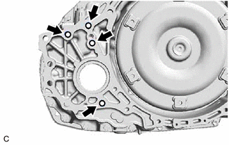
| (c) Remove the 4 transfer and transaxle setting stud bolts from the automatic transaxle assembly. HINT: Perform this procedure only when replacement of the transfer and transaxle setting stud bolt is necessary. |
|
 Components
COMPONENTS ILLUSTRATION *1 AUTOMATIC TRANSMISSION ASSEMBLY *2 TRANSFER AND TRANSAXLE SETTING STUD BOLT *3 TRANSFER ASSEMBLY - - N*m (kgf*cm, ft.*lbf): Specified torque ● ...
 Inspection
INSPECTION PROCEDURE 1. INSPECT PRELOAD (a) Inspect Driven Pinion Preload: (1) Using SST and a torque wrench, measure the preload of the backlash between the driven pinion and ring gear. SST: 09326 ...
Other materials:
Lexus RX (RX 350L, RX450h) 2016-2026 Owners Manual > Lexus RX (RX 350L, RX450h) 2016-2026 Owners Manual: For your information
Main Owner's Manual
Please note that this manual applies to all models and explains all
equipment, including
options. Therefore, you may find some explanations for equipment not installed
on your
vehicle.
All specifications provided in this manual are current at the time of printing.
How ...
Lexus RX (RX 350L, RX450h) 2016-2026 Repair Manual > Lin Communication System: Diagnosis System
DIAGNOSIS SYSTEM DESCRIPTION The main body ECU (multiplex network body ECU) and certification ECU (smart key ECU assembly) control the LIN communication system. LIN communication system data and Diagnostic Trouble Codes (DTCs) can be read through the Data Link Connector 3 (DLC3). When the system see ...
Lexus RX (RX 350L, RX450h) 2016-{YEAR} Owners Manual
- For your information
- Pictorial index
- For safety and security
- Instrument cluster
- Operation of each component
- Driving
- Lexus Display Audio system
- Interior features
- Maintenance and care
- When trouble arises
- Vehicle specifications
- For owners
Lexus RX (RX 350L, RX450h) 2016-{YEAR} Repair Manual

0.0111