Lexus RX (RX 350L, RX450h) 2016-2026 Repair Manual: Inspection
INSPECTION
PROCEDURE
1. INSPECT PRELOAD
(a) Inspect Driven Pinion Preload:
| (1) Using SST and a torque wrench, measure the preload of the backlash between the driven pinion and ring gear. SST: 09326-20011 Preload (at Starting): 0.5 to 0.9 N*m (5 to 9 kgf*cm, 4 to 8 in.*lbf) HINT:
|
|
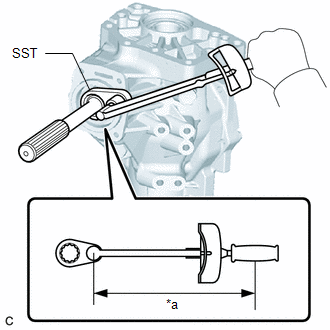
(b) Inspect Total Preload:
(1) Using SST and a torque wrench, measure the total preload.
SST: 09326-20011
Preload (at Starting):
0.3 to 0.5 N*m (3 to 5 kgf*cm, 3 to 4 in.*lbf) + Driven pinion preload
HINT:
-
Calculate the torque wrench reading when changing the fulcrum length of the torque wrench.
Click here
.gif)
-
When using SST (fulcrum length of 50 mm (1.97 in.)) + torque wrench (fulcrum length of 130 mm (5.12 in.)):
0.22 to 0.36 N*m (2.2 to 3.7 kgf*cm, 1.9 to 3.2 in.*lbf) + Driven pinion preload
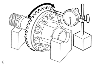
2. INSPECT RING GEAR BACKLASH
| (a) Set a dial indicator perpendicular to a ring gear tooth tip. |
|
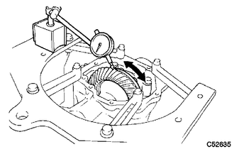
(b) Using a dial indicator, check the ring gear backlash.
Backlash:
0.14 to 0.25 mm (0.00551 to 0.00984 in.)
If the backlash is not within the specification, adjust the side bearing preload or repair as necessary.
NOTICE:
Check at least 3 positions on the circumference of the ring gear.
3. INSPECT TOOTH CONTACT BETWEEN RING GEAR AND DRIVEN PINION
| (a) Apply a light coat of Prussian blue evenly to both sides of all teeth. |
|
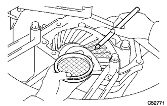
(b) Rotate the ring gear 10 times or more.
(c) Rotate the ring gear to inspect the tooth contact pattern.
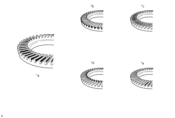
| *a | Proper Contact | *b | Heel Contact |
| *c | Face Contact | *d | Toe Contact |
| *e | Flank Contact | - | - |
NOTICE:
Check at least 4 positions on the circumference of the ring gear.
HINT:
Prussian blue shown in the illustration indicates the tooth contact pattern.
(d) If the tooth contact pattern is not correct, select a new transfer output shaft washer that is thicker or thinner as necessary and recheck.
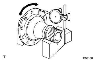
4. INSPECT RUNOUT OF RING GEAR
| (a) Place the transfer ring gear mounting case with ring gear on the V-blocks. |
|
(b) Using a dial indicator, check the runout of the ring gear.
Maximum Runout:
0.06 mm (0.00236 in.)
5. INSPECT TRANSFER RING GEAR MOUNTING CASE
| (a) Place the transfer ring gear mounting case on the V-blocks. |
|
(b) Using a dial indicator, check the runout of the ring gear mounting case.
Maximum Runout:
0.04 mm (0.00157 in.)
 Removal
REMOVAL CAUTION / NOTICE / HINT The necessary procedures (adjustment, calibration, initialization or registration) that must be performed after parts are removed and installed, or replaced during tran ...
 Installation
INSTALLATION PROCEDURE 1. INSTALL TRANSFER ASSEMBLY (a) Install 4 new transfer and transaxle setting stud bolts to the automatic transaxle assembly positions shown in the illustration. *a 69 mm ...
Other materials:
Lexus RX (RX 350L, RX450h) 2016-2026 Repair Manual > Roof Rack(w/ Rear No. 2 Seat): Removal
REMOVAL CAUTION / NOTICE / HINT The necessary procedures (adjustment, calibration, initialization or registration) that must be performed after parts are removed and installed, or replaced during roof rack removal/installation are shown below. Necessary Procedures After Parts Removed/Installed/Repla ...
Lexus RX (RX 350L, RX450h) 2016-2026 Repair Manual > Parking Assist Monitor System: Precaution
PRECAUTION PRECAUTION FOR DISCONNECTING CABLE FROM NEGATIVE BATTERY TERMINAL NOTICE: When disconnecting the cable from the negative (-) battery terminal, initialize the following systems after the cable is reconnected. System Name See Procedure Lane Control System Pre-collision Sys ...
Lexus RX (RX 350L, RX450h) 2016-{YEAR} Owners Manual
- For your information
- Pictorial index
- For safety and security
- Instrument cluster
- Operation of each component
- Driving
- Lexus Display Audio system
- Interior features
- Maintenance and care
- When trouble arises
- Vehicle specifications
- For owners
Lexus RX (RX 350L, RX450h) 2016-{YEAR} Repair Manual

0.009