Lexus RX (RX 350L, RX450h) 2016-2026 Repair Manual: Removal
REMOVAL
CAUTION / NOTICE / HINT
The necessary procedures (adjustment, calibration, initialization or registration) that must be performed after parts are removed and installed, or replaced during camshaft timing gear bolt removal/installation are shown below.
Necessary Procedures After Parts Removed/Installed/Replaced| Replaced Part or Performed Procedure | Necessary Procedure | Effect/Inoperative Function when Necessary Procedure not Performed | Link |
|---|---|---|---|
| Battery terminal is disconnected/reconnected | Memorize steering angle neutral point | Lane Control System | |
| Pre-collision System | |||
| Intelligent Clearance Sonar System*1 | |||
| Parking Assist Monitor System | | ||
| Panoramic View Monitor System | | ||
| Lighting System (w/ Automatic Headlight Beam Level Control System) | | ||
| Initialize back door lock | Power Door Lock Control System | | |
| Reset back door close position | Power Back Door System (w/ Outside Door Control Switch) | | |
| Replacement of ECM | Vehicle Identification Number (VIN) registration | MIL comes on | |
| ECU communication ID registration (Immobiliser system) | Engine start function | | |
| Perform the following procedures in the order shown (If possible, read the transaxle compensation code from the previous ECM):
|
| | |
| Perform the following procedures in the order shown (If impossible, read the transaxle compensation code from the previous ECM):
| |||
| Perform code registration (Immobiliser system) |
| | |
| Inspection after repair |
| |
| Replacement of brake actuator assembly | Operate the electric parking brake switch assembly | Parking brake indicator light (red) blinks when the engine switch is first turned on (IG) | |
| Perform yaw rate and acceleration sensor zero point calibration and store system information. |
| |
*1: When performing learning using the Techstream.
Click here .gif)
PROCEDURE
1. REMOVE FRONT WHEEL RH
Click here
2. REMOVE FRONT FENDER APRON SEAL RH
Click here
3. REMOVE CAMSHAFT TIMING OIL CONTROL SOLENOID ASSEMBLY (for Exhaust Side of Bank 2)
Click here
4. SET NO. 1 CYLINDER TO TDC/COMPRESSION
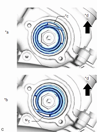
| (a) Turn the crankshaft pulley clockwise until its timing mark (cutout) is aligned with the timing mark on the timing chain cover assembly as shown in the illustration. |
|
.png)
| (b) Check that the cutout of the camshaft timing gear assembly is at the top. HINT: If the cutout of the camshaft timing gear assembly (for exhaust side) is not at the top, turn the crankshaft 360° clockwise and align the timing mark (cutout) of the crankshaft pulley with the timing mark on the timing chain cover assembly again. |
|
5. REMOVE CAMSHAFT TIMING GEAR BOLT (for Exhaust Side of Bank 2)
| (a) While holding the crankshaft pulley, remove the camshaft timing gear bolt. NOTICE:
|
|
6. REMOVE WINDSHIELD WIPER MOTOR AND LINK ASSEMBLY
Click here
7. REMOVE OUTER COWL TOP PANEL SUB-ASSEMBLY
Click here
8. REMOVE NO. 2 ENGINE UNDER COVER
Click here
9. REMOVE ECM
Click here
10. REMOVE INTAKE AIR SURGE TANK ASSEMBLY
Click here
11. REMOVE INLET AIR CLEANER ASSEMBLY
Click here
12. REMOVE BATTERY
for 2WD: Click here
for AWD: Click here
13. REMOVE BATTERY CARRIER SUB-ASSEMBLY
for 2WD: Click here
for AWD: Click here
14. REMOVE BATTERY BRACKET REINFORCEMENT
for 2WD: Click here
for AWD: Click here
15. REMOVE FUEL PUMP PROTECTOR
Click here
16. REMOVE WIRE HARNESS CLAMP BRACKET
for 2WD: Click here
for AWD: Click here
17. REMOVE BRAKE ACTUATOR ASSEMBLY
Click here
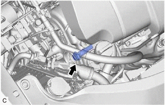
18. DISCONNECT NO. 1 RADIATOR HOSE
Click here
19. INSTALL ENGINE SUPPORT BRIDGE
for 2WD: Click here
for AWD: Click here
20. REMOVE NO. 2 ENGINE MOUNTING STAY RH
Click here
21. REMOVE ENGINE MOUNTING INSULATOR SUB-ASSEMBLY RH
Click here
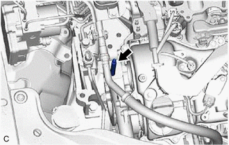
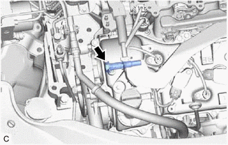
22. REMOVE CAMSHAFT TIMING OIL CONTROL SOLENOID ASSEMBLY (for Intake Side of Bank 2)
Click here
23. REMOVE CAMSHAFT TIMING GEAR BOLT (for Intake Side of Bank 2)
| (a) Using an 8 mm socket wrench, remove the stud bolt. |
|
(b) Make sure that the No. 1 cylinder is at TDC/compression.
HINT:
Check that the cutout of the camshaft timing gear assembly is at the top and align the timing mark (cutout) of the crankshaft pulley with the timing mark on the timing chain cover assembly.
| (c) While holding the crankshaft pulley, remove the camshaft timing gear bolt. NOTICE:
|
|
 On-vehicle Inspection
ON-VEHICLE INSPECTION PROCEDURE 1. REMOVE CAMSHAFT TIMING GEAR BOLT Click here 2. INSPECT CAMSHAFT TIMING GEAR BOLT (a) for intake side: (1) Check the stroke of the plunger in the center of the ...
 Installation
INSTALLATION PROCEDURE 1. INSTALL CAMSHAFT TIMING GEAR BOLT (for Intake Side of Bank 2) NOTICE: There are different types of camshaft timing gear bolts. Make sure to check the identification mark to d ...
Other materials:
Lexus RX (RX 350L, RX450h) 2016-2026 Repair Manual > Intuitive Parking Assist System (w/ Intelligent Clearance Sonar System): Front Left Center Sensor (C1AE2)
DESCRIPTION The front center ultrasonic sensor LH is installed to the front bumper. The clearance warning ECU assembly detects obstacles based on signals received from the front center ultrasonic sensor LH. If the front center ultrasonic sensor LH has an open circuit or other malfunction, it will no ...
Lexus RX (RX 350L, RX450h) 2016-2026 Repair Manual > Power Tilt And Power Telescopic Steering Column System: IG Power Source Circuit
DESCRIPTION When the engine switch is turned on (IG), the IG power source circuit supplies positive (+) voltage to the multiplex tilt and telescopic ECU. The multiplex tilt and telescopic ECU also receives engine switch signals via this circuit. WIRING DIAGRAM CAUTION / NOTICE / HINT HINT: Inspect ...
Lexus RX (RX 350L, RX450h) 2016-{YEAR} Owners Manual
- For your information
- Pictorial index
- For safety and security
- Instrument cluster
- Operation of each component
- Driving
- Lexus Display Audio system
- Interior features
- Maintenance and care
- When trouble arises
- Vehicle specifications
- For owners
Lexus RX (RX 350L, RX450h) 2016-{YEAR} Repair Manual

0.0094