Lexus RX (RX 350L, RX450h) 2016-2026 Repair Manual: Installation
INSTALLATION
PROCEDURE
1. INSTALL TORQUE CONVERTER ASSEMBLY
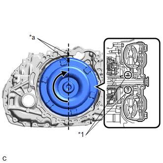
| (a) Turn the front oil pump drive gear so that either key is at the top and place a matchmark on the transaxle housing to indicate the position of the key. |
|
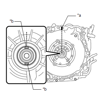
| (b) Place a matchmark on the torque converter assembly so that the position of its groove is clearly indicated. |
|
| (c) Align the matchmark on the torque converter assembly with the one on the transaxle housing and engage the splines of the input shaft with the turbine runner splines. NOTICE:
|
|
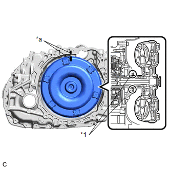
| (d) Rotate the torque converter assembly approximately 180° and engage the splines of the stator shaft with the stator assembly. NOTICE:
|
|
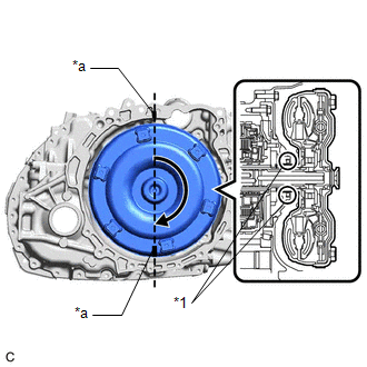
| (e) Rotate the torque converter assembly approximately 180° again, align the matchmark on the torque converter assembly with the one on the transaxle housing and insert the keys of the front oil pump drive gear into the grooves of the torque converter assembly. NOTICE:
|
|
(f) Clean the drive plate and torque converter assembly setting bolt holes.
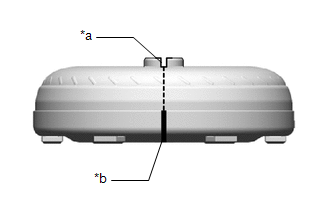
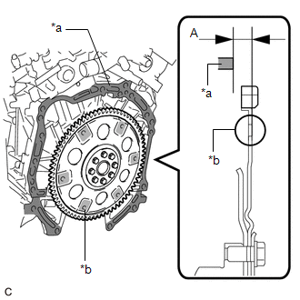
| (g) Using a vernier caliper and straightedge, measure the dimension (A) between the automatic transaxle assembly contact surface of the engine assembly*a and the torque converter assembly contact surface of the drive plate and ring gear sub-assembly*b. NOTICE: Make sure to deduct the thickness of the straightedge. |
|
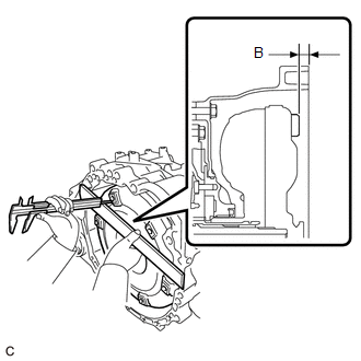
| (h) Using a vernier caliper and straightedge, measure the dimension (B) shown in the illustration and check that the dimension (B) is more than the dimension (A), which was measured in the previous step. Standard: Dimension (A) + 1 mm (0.0394 in.) or more NOTICE:
|
|
2. INSTALL TRANSMISSION BREATHER SKIRT
(a) Install the transmission breather skirt to the automatic transaxle case sub-assembly with the bolt.
Torque:
12 N·m {122 kgf·cm, 9 ft·lbf}
(b) Engage the 3 clamps to install the transmission breather plug.
3. INSTALL NO. 2 TRANSMISSION CONTROL CABLE BRACKET
(a) Install the No. 2 transmission control cable bracket to the automatic transaxle case sub-assembly with the bolt.
Torque:
12 N·m {122 kgf·cm, 9 ft·lbf}
4. INSTALL REAR ENGINE MOUNTING BRACKET
(a) Install the rear engine mounting bracket to the transaxle housing with the 3 bolts.
Torque:
40 N·m {408 kgf·cm, 30 ft·lbf}
5. INSTALL REAR ENGINE MOUNTING INSULATOR
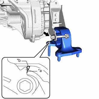
| (a) Install the rear engine mounting insulator to the rear engine mounting bracket with the through bolt. Torque: 71 N·m {724 kgf·cm, 52 ft·lbf} NOTICE: If tightening the bolt before installation of the front frame assembly, ensure that the edge of the protrusion of the bracket is within the width of the rib. |
|
6. INSTALL ENGINE MOUNTING BRACKET LH
(a) Install the engine mounting bracket LH to the automatic transaxle case sub-assembly with the 4 bolts.
Torque:
40 N·m {408 kgf·cm, 30 ft·lbf}
(b) Engage the transmission breather clamp to the engine mounting bracket LH.
7. INSTALL AUTOMATIC TRANSAXLE ASSEMBLY
(a) Apply clutch spline grease to the surface of the crankshaft that contacts the torque converter assembly centerpiece.
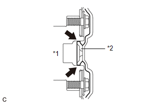
| *1 | Crankshaft |
| *2 | Torque Converter Assembly Centerpiece |
.png) | Clutch Spline Grease |
Clutch Spline Grease:
Toyota Genuine Clutch Spline Grease or equivalent
Maximum Grease Amount:
Approximately 1 g (0.0353 oz)
| (b) Confirm that the knock pins are installed to the engine assembly and are not damaged. |
|
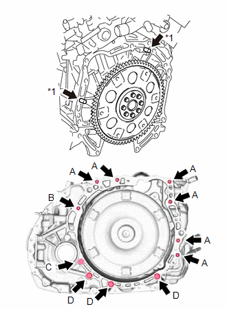
(c) While keeping the engine assembly and automatic transaxle assembly horizontal, align the knock pins with the holes in the automatic transaxle assembly and install the automatic transaxle assembly with the 11 bolts shown in the illustration.
Torque:
Bolt (A) :
64 N·m {653 kgf·cm, 47 ft·lbf}
Bolt (B) :
64 N·m {653 kgf·cm, 47 ft·lbf}
Bolt (C) :
46 N·m {469 kgf·cm, 34 ft·lbf}
Bolt (D) :
43 N·m {438 kgf·cm, 32 ft·lbf}
NOTICE:
- Confirm that the knock pins are installed to the automatic transaxle assembly contact surface of the cylinder block sub-assembly before installing the automatic transaxle assembly.
- Do not forcibly pry on the automatic transaxle assembly.
- Check that the torque converter assembly rotates.
- Bolt (A): 55 mm (2.17 in.)
- Bolt (B): 50 mm (1.97 in.)
- Bolt (C): 41 mm (1.61 in.)
- Bolt (D): 33 mm (1.30 in.)
8. INSTALL ENGINE MOUNTING INSULATOR LH
| (a) Install the engine mounting insulator LH to the vehicle body with the 5 bolts. Torque: 71 N·m {724 kgf·cm, 52 ft·lbf} NOTICE: Tightening order: Temporarily tighten bolt (A) → Fully tighten bolt (B) → Fully tighten bolt (A), (C), (D) and (E) |
|
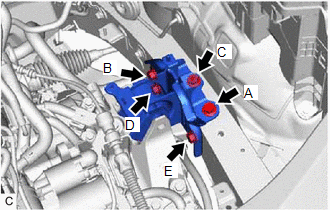
(b) Install the through bolt and nut.
Torque:
40 N·m {408 kgf·cm, 30 ft·lbf}
HINT:
When tightening the through bolt, keep the nut from rotating.
(c) Install the engine wire to the engine mounting insulator LH with the nut.
Torque:
8.4 N·m {86 kgf·cm, 74 in·lbf}
(d) Engage the clamp.
9. INSTALL FRONT ENGINE MOUNTING BRACKET
(a) Install the front engine mounting bracket to the transaxle housing with the 3 bolts.
Torque:
64 N·m {653 kgf·cm, 47 ft·lbf}
10. INSTALL FRONT ENGINE MOUNTING INSULATOR
Click here .gif)
11. CONNECT NO. 1 TRANSMISSION OIL COOLER HOSE
Click here
12. INSTALL FRONT FRAME ASSEMBLY
Click here
13. CONNECT FRONT ENGINE MOUNTING INSULATOR
Click here
14. CONNECT REAR ENGINE MOUNTING INSULATOR
Click here
15. INSTALL DRIVE PLATE AND TORQUE CONVERTER ASSEMBLY SETTING BOLT
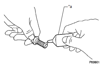
(a) Remove any adhesive remaining the 6 drive plate and torque converter assembly setting bolts.
| (b) Apply a few drops of adhesive to 2 or 3 threads at the tip of each of the 6 drive plate and torque converter assembly setting bolts. Adhesive: Toyota Genuine Adhesive 1324, Three Bond 1324 or equivalent NOTICE: Make sure to install the 6 drive plate and torque converter assembly setting bolts immediately after applying adhesive to prevent foreign matter from attaching to them. |
|
(c) Turn the crankshaft to gain access to the installation locations of the 6 drive plate and torque converter assembly setting bolts and install each drive plate and torque converter assembly setting bolt while holding the crankshaft pulley bolt with a wrench.
Torque:
41 N·m {418 kgf·cm, 30 ft·lbf}
NOTICE:
First install the black colored drive plate and torque converter assembly setting bolt, and then the remaining 5 silver colored drive plate and torque converter assembly setting bolts.
16. INSTALL FLYWHEEL HOUSING UNDER COVER
(a) Install the flywheel housing under cover to the automatic transaxle case sub-assembly with the 2 bolts.
Torque:
10 N·m {102 kgf·cm, 7 ft·lbf}
17. REMOVE ENGINE SUPPORT BRIDGE
(a) Remove SST from the vehicle body.
NOTICE:
Prevent SST from contacting the vehicle body or windshield glass.
18. REMOVE ENGINE HANGER
(a) Remove the 2 bolts and No. 2 engine hanger from the cylinder head LH.
(b) Remove the bolt and No. 1 engine hanger from the cylinder head RH.
19. INSTALL FUEL PUMP PROTECTOR
Click here
20. INSTALL WIRE HARNESS CLAMP BRACKET
(a) Install the wire harness clamp bracket to the cylinder head RH with the bolt.
Torque:
13 N·m {133 kgf·cm, 10 ft·lbf}
(b) Engage the hose clamp and 3 wire harness clamps.
(c) Connect the air fuel ratio sensor (for Bank 1) connector.
21. INSTALL AIR SURGE TANK TO INTAKE MANIFOLD GASKET
Click here
22. INSTALL INTAKE AIR SURGE TANK ASSEMBLY
Click here
23. CONNECT PURGE VALVE (PURGE VSV)
Click here
24. CONNECT VENTILATION HOSE
Click here
25. CONNECT NO. 1 RADIATOR HOSE
Click here
26. INSTALL NO. 1 EXHAUST PIPE SUPPORT BRACKET
Click here
27. INSTALL FRONT EXHAUST PIPE ASSEMBLY
Click here
28. INSTALL NO. 1 EXHAUST PIPE SUPPORT BRACKET (for Lower Side)
Click here
29. INSTALL FRONT DRIVE SHAFT ASSEMBLY
Click here
30. INSTALL FRONT FENDER APRON SEAL LH
Click here
31. INSTALL SUSPENSION TOWER DAMPER (w/ Suspension Tower Damper)
Click here
32. INSTALL FRONT LOWER BUMPER ABSORBER
Click here
33. INSTALL NO. 3 ENGINE UNDER COVER
Click here
34. INSTALL FRONT WHEEL OPENING EXTENSION PAD LH
Click here
35. INSTALL FRONT STABILIZER BAR
Click here
36. CONNECT WIRE HARNESS
(a) Connect the wire harness to the automatic transaxle case sub-assembly with the bolt.
Torque:
19.1 N·m {195 kgf·cm, 14 ft·lbf}
(b) Connect the transmission wire connector and park/neutral position switch assembly connector.
37. INSTALL NO. 2 VACUUM SWITCHING VALVE ASSEMBLY
Click here
38. CONNECT TRANSMISSION CONTROL CABLE ASSEMBLY
Click here
39. INSTALL BATTERY BRACKET REINFORCEMENT
(a) Install the battery bracket reinforcement to the vehicle body with the 2 bolts.
Torque:
20 N·m {204 kgf·cm, 15 ft·lbf}
40. INSTALL BATTERY CARRIER SUB-ASSEMBLY
(a) Install the battery carrier sub-assembly to the vehicle body with the 6 bolts.
Torque:
20 N·m {204 kgf·cm, 15 ft·lbf}
(b) Engage the 2 clamps.
41. INSTALL BATTERY
Click here
42. INSTALL ECM
Click here
43. INSTALL STARTER ASSEMBLY
Click here
44. INSTALL OUTER COWL TOP PANEL SUB-ASSEMBLY
Click here
45. INSTALL FRONT WIPER MOTOR AND LINK ASSEMBLY
Click here
46. INSTALL V-BANK COVER SUB-ASSEMBLY
Click here
47. CONNECT CABLE TO NEGATIVE BATTERY TERMINAL
NOTICE:
When disconnecting the cable, some systems need to be initialized after the cable is reconnected.
Click here
48. ADD ENGINE COOLANT
Click here
49. INSPECT FOR COOLANT LEAK
Click here
50. CHECK AUTOMATIC TRANSAXLE SYSTEM
NOTICE:
If automatic transaxle parts have been replaced, refer to Parts Replacement Compensation Table to determine if any additional operations are necessary.
Click here
 Components
COMPONENTS ILLUSTRATION *1 OUTER COWL TOP PANEL SUB-ASSEMBLY - - N*m (kgf*cm, ft.*lbf): Specified torque - - ILLUSTRATION *1 FRONT WHEEL OPENING EXTENSION PAD LH *2 N ...
 Removal
REMOVAL CAUTION / NOTICE / HINT The necessary procedures (adjustment, calibration, initialization or registration) that must be performed after parts are removed and installed, or replaced during auto ...
Other materials:
Lexus RX (RX 350L, RX450h) 2016-2026 Owners Manual > Using the air conditioning
system and defogger: Heated steering wheel/
seat heaters/
seat ventilators
Heated steering wheel and seat heaters heat the side grips of the
steering
wheel and seats, respectively. Seat ventilators maintain good ventilation using
a fan built into the seats.
WARNING
Care should be taken to prevent injury if anyone in the following
categories comes in
contact w ...
Lexus RX (RX 350L, RX450h) 2016-2026 Repair Manual > Fuel Lid Opener System: Precaution
PRECAUTION PRECAUTION FOR DISCONNECTING CABLE FROM NEGATIVE BATTERY TERMINAL NOTICE: When disconnecting the cable from the negative (-) battery terminal, initialize the following systems after the cable is reconnected. System Name See Procedure Lane Control System Pre-collision Sys ...
Lexus RX (RX 350L, RX450h) 2016-{YEAR} Owners Manual
- For your information
- Pictorial index
- For safety and security
- Instrument cluster
- Operation of each component
- Driving
- Lexus Display Audio system
- Interior features
- Maintenance and care
- When trouble arises
- Vehicle specifications
- For owners
Lexus RX (RX 350L, RX450h) 2016-{YEAR} Repair Manual

0.012