Lexus RX (RX 350L, RX450h) 2016-2026 Repair Manual: Monitor Drive Pattern
MONITOR DRIVE PATTERN
MONITOR DRIVE PATTERN FOR ECT
CAUTION:
Perform the following procedure on a level surface while strictly observing all traffic laws and speed limits.
HINT:
Performing this drive pattern is one method to simulate ECM (ECT) malfunction detection conditions. Some DTCs may not be detected through ordinary, everyday driving. Also, some DTCs may not be detected through this drive pattern.
(a) Preparation for driving
(1) Warm up the engine sufficiently (engine coolant temperature of 60°C (140°F) or higher).
(2) Drive the vehicle when the ambient temperature is -10°C (14°F) or higher.
Some malfunctions are not detected when the ambient temperature is less than -10°C (14°F).
(b) Drive pattern
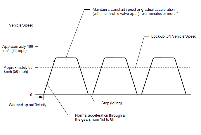
*: Drive at a speed in the highest gear that will cause lock-up to engage. The vehicle can be driven at a speed lower than the speed shown in the above diagram under lock-up.
(1) Drive the vehicle through all of the gears.
Stop → 1st → 2nd → 3rd → 4th → 5th → 6th → 7th → 8th → 8th (lock-up ON).
HINT:
Lock-up will be engaged while driving in 3rd gear or higher.
(2) Perform an engine braking test with the shift lever in M. While driving in M8 with 8th gear lock-up, move the shift lever to "-" and down-shift from 8th → 7th, 7th → 6th, 6th → 5th, 5th → 4th, 4th → 3rd, 3rd → 2nd and 2nd → 1st.
Check that engine braking is normal for every down-shift.
(3) Repeat the above drive pattern 3 times or more.
NOTICE:
-
When using the Techstream, the monitor status can be checked in the Data List.
Click here
.gif)
- In the event that the drive pattern must be interrupted (due to traffic conditions or other factors), the drive pattern can be resumed and, in most cases, the monitor can be completed.
- Perform this drive pattern on a level road as much as possible and strictly observe the posted speed limits and traffic laws while driving.
- It is necessary to drive the vehicle for approximately 30 minutes to detect DTC P071000 (ATF temperature sensor malfunction).
 Initialization
INITIALIZATION RESET TRANSAXLE COMPENSATION CODE NOTICE:
If the following parts have been replaced, initialize the ECM and perform Reset Memory and Perform Road Test to Allow ECM to Learn.
ECM
...
 Problem Symptoms Table
PROBLEM SYMPTOMS TABLE HINT:
Use the table below to help determine the cause of problem symptoms. If multiple suspected areas are listed, the potential causes of the symptoms are listed in order of ...
Other materials:
Lexus RX (RX 350L, RX450h) 2016-2026 Repair Manual > Power Mirror Control System (w/ Memory): Precaution
PRECAUTION PRECAUTION FOR DISCONNECTING CABLE FROM NEGATIVE BATTERY TERMINAL NOTICE: When disconnecting the cable from the negative (-) battery terminal, initialize the following systems after the cable is reconnected. System Name See Procedure Lane Control System Pre-collision Sys ...
Lexus RX (RX 350L, RX450h) 2016-2026 Repair Manual > Exhaust Pipe: Removal
REMOVAL CAUTION / NOTICE / HINT The necessary procedures (adjustment, calibration, initialization or registration) that must be performed after parts are removed and installed, or replaced during front exhaust pipe assembly, front No. 3 exhaust pipe sub-assembly, center exhaust pipe assembly (TWC: R ...
Lexus RX (RX 350L, RX450h) 2016-{YEAR} Owners Manual
- For your information
- Pictorial index
- For safety and security
- Instrument cluster
- Operation of each component
- Driving
- Lexus Display Audio system
- Interior features
- Maintenance and care
- When trouble arises
- Vehicle specifications
- For owners
Lexus RX (RX 350L, RX450h) 2016-{YEAR} Repair Manual

0.0137