Lexus RX (RX 350L, RX450h) 2016-2026 Repair Manual: Cooling Fan Circuit
DESCRIPTION
The ECM calculates an appropriate cooling fan speed based on the engine coolant temperature, air conditioning switch condition, refrigerant pressure, engine speed and vehicle speed. The cooling fan ECUs control each cooling fan speed based on the duty cycle calculated by the ECM. By optimally controlling the cooling fan speed via the cooling fan ECUs based on the conditions of the vehicle, the ECM can achieve both high cooling performance and quietness.
WIRING DIAGRAM
Refer to the System Diagram.
Click here .gif)
CAUTION / NOTICE / HINT
NOTICE:
- Inspect the fuses for circuits related to this system before performing the following procedure.
-
Before replacing the ECM, refer to Registration.
Click here
PROCEDURE
| 1. | PERFORM ACTIVE TEST USING TECHSTREAM (CONTROL THE ENGINE COOLING FAN DUTY RATIO) |
(a) Connect the Techstream to the DLC3.
(b) Turn the engine switch on (IG).
(c) Turn the Techstream on.
(d) Enter the following menus: Powertrain / Engine / Active Test / Control the Engine Cooling Fan Duty Ratio.
Powertrain > Engine > Active Test| Tester Display |
|---|
| Control the Engine Cooling Fan Duty Ratio |
(e) Perform the Active Test according to the display on the Techstream.
OK:
| Active Test Operation | Fan Operation |
|---|---|
| 30 - 100% | Cooling fans operate |
| 0% | Cooling fans stop |
| Result | Proceed to |
|---|---|
| OK | A |
| NG (Cooling fans do not operate) | B |
| NG (Cooling fans do not stop) | C |
| A |  | PROCEED TO NEXT SUSPECTED AREA SHOWN IN PROBLEM SYMPTOMS TABLE |
| C | | GO TO STEP 10 |
|

| 2. | CHECK COOLING FAN SYSTEM |
(a) Disconnect the D2 ECM connector.
(b) Turn the engine switch on (IG).
(c) Check the operation of the cooling fans.
OK:
Cooling fans operate.
| OK | | REPLACE ECM |
|
| 3. | INSPECT COOLING FAN MOTOR (COOLING FAN MOTOR LH AND COOLING FAN MOTOR RH) |
(a) Inspect the cooling fan motor LH and cooling fan motor RH.
Click here
| Result | Proceed to |
|---|---|
| OK | A |
| NG (Cooling fan motor LH) | B |
| NG (Cooling fan motor RH) | C |
| B | | REPLACE COOLING FAN MOTOR LH |
| C | | REPLACE COOLING FAN MOTOR RH |
|
| 4. | CHECK HARNESS AND CONNECTOR (COOLING FAN ECU POWER SOURCE CIRCUIT) |
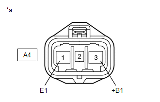
(a) Disconnect the A4 cooling fan ECU connector.
(b) Turn the engine switch on (IG).
| (c) Measure the voltage according to the value(s) in the table below. Standard Voltage:
|
|
| NG | | GO TO STEP 6 |
|
| 5. | CHECK HARNESS AND CONNECTOR (ECM - COOLING FAN ECU) |
(a) Disconnect the D2 ECM connector.
(b) Disconnect the A4 cooling fan ECU connector.
(c) Measure the resistance according to the value(s) in the table below.
Standard Resistance (Check for Short):
| Tester Connection | Condition | Specified Condition |
|---|---|---|
| D2-136 (RFC) or A4-2 (SI) - Body ground | Always | 10 kΩ or higher |
| OK | | REPLACE COOLING FAN ECU |
| NG | | REPAIR OR REPLACE HARNESS OR CONNECTOR (ECM - COOLING FAN ECU) |
| 6. | CHECK HARNESS AND CONNECTOR (COOLING FAN ECU - BODY GROUND) |
(a) Disconnect the A4 cooling fan ECU connector.
(b) Measure the resistance according to the value(s) in the table below.
Standard Resistance (Check for Open):
| Tester Connection | Condition | Specified Condition |
|---|---|---|
| A4-1 (E1) - Body ground | Always | Below 1 Ω |
| NG | | REPAIR OR REPLACE HARNESS OR CONNECTOR (COOLING FAN ECU - BODY GROUND) |
|
| 7. | INSPECT FAN RELAY |
(a) Inspect the FAN relay.
Click here
| NG | | REPLACE FAN RELAY |
|
| 8. | CHECK HARNESS AND CONNECTOR (FAN RELAY POWER SOURCE CIRCUIT) |
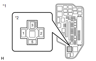
(a) Remove the FAN relay from the No. 1 engine room relay block and No. 1 junction block assembly.
(b) Turn the engine switch on (IG).
| (c) Measure the voltage according to the value(s) in the table below. Standard Voltage:
|
|
| NG | | REPAIR OR REPLACE HARNESS OR CONNECTOR (FAN RELAY POWER SOURCE CIRCUIT) |
|
| 9. | CHECK HARNESS AND CONNECTOR (COOLING FAN ECU - FAN RELAY) |
(a) Disconnect the A4 cooling fan ECU connector.
(b) Remove the FAN relay from the No. 1 engine room relay block and No. 1 junction block assembly.
(c) Measure the resistance according to the value(s) in the table below.
Standard Resistance (Check for Open):
| Tester Connection | Condition | Specified Condition |
|---|---|---|
| A4-3(+B1) - 5 (FAN relay) | Always | Below 1 Ω |
Standard Resistance (Check for Short):
| Tester Connection | Condition | Specified Condition |
|---|---|---|
| A4-3 (+B1) or 5 (FAN relay) - Body ground | Always | 10 kΩ or higher |
| OK | | REPAIR OR REPLACE HARNESS OR CONNECTOR (FAN RELAY - BODY GROUND) |
| NG | | REPAIR OR REPLACE HARNESS OR CONNECTOR (COOLING FAN ECU - FAN RELAY) |
| 10. | CHECK HARNESS AND CONNECTOR (ECM - COOLING FAN ECU) |
(a) Disconnect the D2 ECM connector.
(b) Disconnect the A4 cooling fan ECU connector.
(c) Measure the resistance according to the value(s) in the table below.
Standard Resistance (Check for Open):
| Tester Connection | Condition | Specified Condition |
|---|---|---|
| D2-136 (RFC) - A4-2 (SI) | Always | Below 1 Ω |
| NG | | REPAIR OR REPLACE HARNESS OR CONNECTOR (ECM - COOLING FAN ECU) |
|
| 11. | CHECK HARNESS AND CONNECTOR (COOLING FAN MOTOR LH - BODY GROUND) |
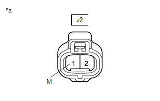
(a) Disconnect the z2 cooling fan motor LH connector.
| (b) Measure the resistance according to the value(s) in the table below. Standard Resistance (Check for Short):
|
|
| NG | | REPLACE COOLING FAN MOTOR LH |
|
| 12. | CHECK HARNESS AND CONNECTOR (COOLING FAN MOTOR RH - BODY GROUND) |
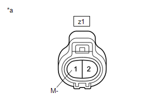
(a) Disconnect the z1 cooling fan motor RH connector.
| (b) Measure the resistance according to the value(s) in the table below. Standard Resistance (Check for Short):
|
|
| OK | | REPLACE COOLING FAN ECU |
| NG | | REPLACE COOLING FAN MOTOR RH |
 On-vehicle Inspection
ON-VEHICLE INSPECTION PROCEDURE 1. INSPECT COOLING FAN SYSTEM CAUTION: To prevent injury due to contact with an operating cooling fan, keep your hands and clothing away from the cooling fans when insp ...
 Cooling System
On-vehicle InspectionON-VEHICLE INSPECTION CAUTION / NOTICE / HINT CAUTION: Do not remove the radiator cap sub-assembly while the engine and radiator assembly are still hot. Pressurized, hot engine co ...
Other materials:
Lexus RX (RX 350L, RX450h) 2016-2026 Repair Manual > Air Conditioning System: Initialization
INITIALIZATION INITIALIZATION SERVO MOTOR (a) Turn the engine switch off. (b) Connect the Techstream to the DLC3. (c) Turn the engine switch on (IG). (d) Press the A/C OFF switch. (e) Turn the Techstream on. (f) Enter the following menus: Body Electrical / Air Conditioner / Utility / Servomotor Init ...
Lexus RX (RX 350L, RX450h) 2016-2026 Repair Manual > Washer Motor: Removal
REMOVAL PROCEDURE 1. REMOVE FRONT WHEEL RH Click here 2. REMOVE FRONT FENDER MOULDING SUB-ASSEMBLY RH HINT: Use the same procedure as for the LH side. Click here 3. REMOVE FRONT WHEEL OPENING EXTENSION PAD RH (a) Remove the 2 screws and front wheel opening extension pad RH. 4. REM ...
Lexus RX (RX 350L, RX450h) 2016-{YEAR} Owners Manual
- For your information
- Pictorial index
- For safety and security
- Instrument cluster
- Operation of each component
- Driving
- Lexus Display Audio system
- Interior features
- Maintenance and care
- When trouble arises
- Vehicle specifications
- For owners
Lexus RX (RX 350L, RX450h) 2016-{YEAR} Repair Manual

0.0108