Lexus RX (RX 350L, RX450h) 2016-2026 Repair Manual: Installation
INSTALLATION
PROCEDURE
1. INSTALL LOWER RADIATOR SUPPORT
(a) Install the 2 lower radiator supports to the radiator assembly.
2. INSTALL RADIATOR SUPPORT CUSHION
(a) Install the 2 radiator support cushions to the radiator assembly.
3. INSTALL RADIATOR ASSEMBLY
(a) Engage the 3 guides.
(b) Engage the 3 claws to install the fan shroud assembly to the radiator assembly.
NOTICE:
Do not damage the radiator assembly when installing the fan shroud assembly.
(c) Connect the radiator reserve tank hose to the radiator assembly.
(d) Install the radiator assembly with the fan shroud assembly to the vehicle body.
NOTICE:
Do not apply excessive force to the cooler condenser assembly or pipe when installing the radiator assembly with the fan shroud assembly.
(e) Engage the 4 wire harness clamps.
(f) Connect the cooling fan ECU connector.
(g) Engage the 2 guides.
(h) Engage the 2 claws to install the cooler condenser assembly to the radiator assembly.
NOTICE:
Make sure not to damage the cooler condenser assembly when installing the radiator assembly.
4. CONNECT OUTLET NO. 1 OIL COOLER HOSE
(a) Connect the outlet No. 1 oil cooler hose and slide the clip to secure it.
5. CONNECT INLET NO. 1 OIL COOLER HOSE
(a) Connect the inlet No. 1 oil cooler hose and slide the clip to secure it.
(b) Engage the clamp to connect the inlet No. 1 oil cooler hose to the fan shroud assembly.
6. CONNECT NO. 2 RADIATOR HOSE
(a) Connect the No. 2 radiator hose and slide the clip to secure it.
(b) Engage the clamp and connect the No. 2 radiator hose to the fan shroud assembly.
7. CONNECT NO. 1 RADIATOR HOSE
(a) Connect the No. 1 radiator hose and slide the clip to secure it.
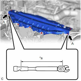
8. INSTALL UPPER RADIATOR SUPPORT SUB-ASSEMBLY
(a) Temporarily install the upper radiator support sub-assembly with the 7 bolts.
| (b) Using a 10 mm union nut wrench, fully tighten the bolt (A). Torque: Specified tightening torque : 12 N·m {122 kgf·cm, 9 ft·lbf} HINT:
|
|
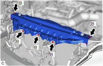
| (c) Fully tighten the bolt (B). Torque: 12 N·m {122 kgf·cm, 9 ft·lbf} |
|
(d) Engage the 4 clamps and connect the wire harness to the upper radiator support sub-assembly.
(e) w/ Smog Ventilation Sensor:
(1) Connect the smog ventilation sensor connector.
9. INSTALL INLET AIR CLEANER ASSEMBLY
Click here .gif)
10. INSTALL HOOD LOCK ASSEMBLY
Click here
11. INSTALL HOOD LOCK RELEASE LEVER PROTECTOR
Click here
12. INSTALL HOOD LOCK CONTROL CABLE COVER
Click here
13. INSTALL FRONT BUMPER COVER
Click here
14. INSTALL BATTERY
for 2WD: Click here
for AWD: Click here
15. CONNECT CABLE TO NEGATIVE BATTERY TERMINAL
NOTICE:
When disconnecting the cable, some systems need to be initialized after the cable is reconnected.
Click here
16. ADD ENGINE COOLANT
Click here
17. INSPECT FOR COOLANT LEAK
Click here
18. INSTALL NO. 1 ENGINE UNDER COVER
Click here
19. INSTALL NO. 3 ENGINE UNDER COVER
Click here
20. INSTALL FRONT WHEEL OPENING EXTENSION PAD RH
Click here
21. INSTALL FRONT WHEEL OPENING EXTENSION PAD LH
Click here
 On-vehicle Inspection
ON-VEHICLE INSPECTION CAUTION / NOTICE / HINT CAUTION: Do not remove the radiator cap sub-assembly while the engine and radiator assembly are still hot. Pressurized, hot engine coolant and steam may b ...
 Removal
REMOVAL CAUTION / NOTICE / HINT The necessary procedures (adjustment, calibration, initialization or registration) that must be performed after parts are removed and installed, or replaced during radi ...
Other materials:
Lexus RX (RX 350L, RX450h) 2016-2026 Repair Manual > Lighting System (w/ Automatic Headlight Beam Level Control System): Headlight LH Circuit (B2439,B243A)
DESCRIPTION The No. 1 headlight ECU sub-assembly LH and No. 1 headlight ECU sub-assembly RH internally boost the power supply voltage to ensure a constant supplied current for the lo/hi beam LED of their respective headlight. By monitoring the LED power supply voltage, abnormal current and malfuncti ...
Lexus RX (RX 350L, RX450h) 2016-2026 Repair Manual > Lighting System (w/o Automatic Headlight Beam Level Control System): Outside Handle Foot Light Circuit
DESCRIPTION The main body ECU (multiplex network body ECU) controls the outside handle foot lights. WIRING DIAGRAM CAUTION / NOTICE / HINT NOTICE: Before replacing the main body ECU (multiplex network body ECU), refer to Registration. Click here PROCEDURE 1. PERFORM ACTIVE TEST USING TECHS ...
Lexus RX (RX 350L, RX450h) 2016-{YEAR} Owners Manual
- For your information
- Pictorial index
- For safety and security
- Instrument cluster
- Operation of each component
- Driving
- Lexus Display Audio system
- Interior features
- Maintenance and care
- When trouble arises
- Vehicle specifications
- For owners
Lexus RX (RX 350L, RX450h) 2016-{YEAR} Repair Manual

0.012