Lexus RX (RX 350L, RX450h) 2016-2026 Repair Manual: Removal
REMOVAL
CAUTION / NOTICE / HINT
The necessary procedures (adjustment, calibration, initialization or registration) that must be performed after parts are removed and installed, or replaced during camshaft timing oil control solenoid assembly removal/installation are shown below.
Necessary Procedures After Parts Removed/Installed/Replaced| Replaced Part or Performed Procedure | Necessary Procedure | Effect/Inoperative Function when Necessary Procedure not Performed | Link |
|---|---|---|---|
| Battery terminal is disconnected/reconnected | Memorize steering angle neutral point | Lane Control System | |
| Pre-collision System | |||
| Intelligent Clearance Sonar System*1 | |||
| Parking Assist Monitor System | | ||
| Panoramic View Monitor System | | ||
| Lighting System (w/ Automatic Headlight Beam Level Control System) | | ||
| Initialize back door lock | Power Door Lock Control System | | |
| Reset back door close position | Power Back Door System (w/ Outside Door Control Switch) | | |
| Replacement of ECM | Vehicle Identification Number (VIN) registration | MIL comes on | |
| ECU communication ID registration (Immobiliser system) | Engine start function | | |
| Perform the following procedures in the order shown (If possible, read the transaxle compensation code from the previous ECM):
|
| | |
| Perform the following procedures in the order shown (If impossible, read the transaxle compensation code from the previous ECM):
| |||
| Perform code registration (Immobiliser system) |
| | |
| Inspection after repair |
| |
| Replacement of brake actuator assembly | Operate the electric parking brake switch assembly | Parking brake indicator light (red) blinks when the engine switch is first turned on (IG) | |
| Perform yaw rate and acceleration sensor zero point calibration and store system information. |
| |
*1: When performing learning using the Techstream.
Click here .gif)
PROCEDURE
1. REMOVE CAMSHAFT TIMING OIL CONTROL SOLENOID ASSEMBLY (for Exhaust Side of Bank 2)
| (a) Disconnect the camshaft timing oil control solenoid assembly connector. |
|
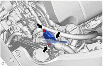
(b) Remove the 2 bolts and camshaft timing oil control solenoid assembly from the timing chain cover assembly.
NOTICE:
If the camshaft timing oil control solenoid assembly has been struck or dropped, replace it.
| (c) Remove the O-ring from the camshaft timing oil control solenoid assembly. NOTICE:
|
|
.png)
2. REMOVE OUTER COWL TOP PANEL SUB-ASSEMBLY
Click here
3. REMOVE NO. 2 ENGINE UNDER COVER
Click here
4. REMOVE ECM
Click here
5. REMOVE INTAKE AIR SURGE TANK ASSEMBLY
Click here
6. REMOVE INLET AIR CLEANER ASSEMBLY
Click here
7. REMOVE BATTERY
for 2WD: Click here
for AWD: Click here
8. REMOVE BATTERY CARRIER SUB-ASSEMBLY
for 2WD: Click here
for AWD: Click here
9. REMOVE BATTERY BRACKET REINFORCEMENT
for 2WD: Click here
for AWD: Click here
10. REMOVE FUEL PUMP PROTECTOR
Click here
11. REMOVE WIRE HARNESS CLAMP BRACKET
for 2WD: Click here
for AWD: Click here
12. REMOVE BRAKE ACTUATOR ASSEMBLY
Click here
13. DISCONNECT NO. 1 RADIATOR HOSE
Click here
14. INSTALL ENGINE SUPPORT BRIDGE
for 2WD: Click here
for AWD: Click here
15. REMOVE NO. 2 ENGINE MOUNTING STAY RH
Click here
16. REMOVE ENGINE MOUNTING INSULATOR SUB-ASSEMBLY RH
Click here
17. REMOVE CAMSHAFT TIMING OIL CONTROL SOLENOID ASSEMBLY (for Intake Side of Bank 2)
| (a) Disconnect the camshaft timing oil control solenoid assembly connector. |
|
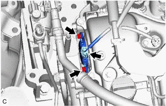
(b) Remove the 2 bolts and camshaft timing oil control solenoid assembly from the timing chain cover assembly.
NOTICE:
If the camshaft timing oil control solenoid assembly has been struck or dropped, replace it.
| (c) Remove the O-ring from the camshaft timing oil control solenoid assembly. NOTICE:
|
|
 On-vehicle Inspection
ON-VEHICLE INSPECTION PROCEDURE 1. INSPECT CAMSHAFT TIMING OIL CONTROL SOLENOID ASSEMBLY (a) Connect the Techstream to the DLC3. (b) Start the engine. (c) Turn the Techstream on. (d) Inspect the camsh ...
 Inspection
INSPECTION PROCEDURE 1. INSPECT CAMSHAFT TIMING OIL CONTROL SOLENOID ASSEMBLY HINT: Use the same procedure for the intake side and exhaust side. (a) Check the resistance. (1) Measure the resistance ...
Other materials:
Lexus RX (RX 350L, RX450h) 2016-2026 Repair Manual > Hood: Reassembly
REASSEMBLY PROCEDURE 1. INSTALL HOOD STAY BRACKET LH Click here 2. INSTALL HOOD SUPPORT ASSEMBLY LH Click here 3. INSTALL HOOD STAY BRACKET RH HINT: Use the same procedure as for the LH side. 4. INSTALL HOOD SUPPORT ASSEMBLY RH HINT: Use the same procedure as for the LH side. 5. CONNECT WASHER H ...
Lexus RX (RX 350L, RX450h) 2016-2026 Repair Manual > Blind Spot Monitor System: Short to +B in Buzzer (C1ABD,C1ABE)
DESCRIPTION
DTC C1ABD is stored when the blind spot monitor sensor RH detects a short to +B in the RCTA buzzer (blind spot monitor buzzer) circuit.
DTC C1ABE is stored when the blind spot monitor sensor RH detects a short to ground or open in the RCTA buzzer (blind spot monitor buzzer) circuit. ...
Lexus RX (RX 350L, RX450h) 2016-{YEAR} Owners Manual
- For your information
- Pictorial index
- For safety and security
- Instrument cluster
- Operation of each component
- Driving
- Lexus Display Audio system
- Interior features
- Maintenance and care
- When trouble arises
- Vehicle specifications
- For owners
Lexus RX (RX 350L, RX450h) 2016-{YEAR} Repair Manual

0.0139