Lexus RX (RX 350L, RX450h) 2016-2026 Repair Manual: Brake Switch "B" Circuit Short to Battery (P070312)
DESCRIPTION
The stop light switch assembly is part of a duplex system that transmits two signals: STP and ST1-. These two signals are used by the ECM to monitor whether or not the brake system is working properly. This DTC indicates that the stop light switch assembly is remaining on. When the stop light switch assembly remains on during "STOP and GO" driving, the ECM interprets this as a fault in the stop light switch assembly. The ECM store this DTC.
| DTC No. | Detection Item | DTC Detection Condition | Trouble Area | MIL | Memory | Note |
|---|---|---|---|---|---|---|
| P070312 | Brake Switch "B" Circuit Short to Battery | The stop light switch assembly remains on even when the vehicle repeats 5 cycles of STOP (less than 3 km/h [1.86 mph]) and GO (30 km/h [18.65 mph] or more) (2 trip detection logic). |
| Does not come on | DTC stored | SAE Code: P0724 |
MONITOR DESCRIPTION
This DTC indicates that the stop light switch assembly is remaining on. When the stop light switch assembly remains on during "STOP and GO" driving, the ECM interprets this as a fault in the stop light switch assembly, stores this DTC. The vehicle must STOP (less than 3 km/h [1.86 mph]) and GO (30 km/h [18.65 mph] or more) 5 times during 2 driving cycles, in order to detect a malfunction.
MONITOR STRATEGY
| Required Sensors/Components (Main) | Stop light switch assembly |
| Required Sensors/Components (Related) | Speed sensor |
| Frequency of Operation | Continuous |
CONFIRMATION DRIVING PATTERN
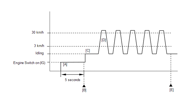
- Connect the Techstream to the DLC3.
- Turn the engine switch on (IG) and turn the Techstream on.
- Clear the DTCs (even if no DTCs are stored, perform the clear DTC procedure).
- Turn the engine switch off and wait for at least 30 seconds.
- Turn the engine switch on (IG) and turn the Techstream on [A].
- Wait 5 seconds.
- Enter the following menus: Powertrain / Engine / Trouble Codes [B].
-
Read the pending DTCs.
HINT:
- If a pending DTC is output, the system is malfunctioning.
- If a pending DTC is not output, perform the following procedure.
- Enter the following menus: Powertrain / Engine / Utility / All Readiness.
- Input the DTC: P070312.
-
Check the DTC judgment result.
Techstream Display
Description
NORMAL
- DTC judgment completed
- System normal
ABNORMAL
- DTC judgment completed
- System abnormal
INCOMPLETE
- DTC judgment not completed
- Perform driving pattern after confirming DTC enabling conditions
N/A
- Unable to perform DTC judgment
- Number of DTCs which do not fulfill DTC preconditions has reached ECU memory limit
HINT:
- If the judgment result shows NORMAL, the system is normal.
- If the judgment result shows ABNORMAL, the system has a malfunction.
- If the judgment result shows INCOMPLETE or N/A, perform steps [C] through [E].
- Start the engine [C].
-
Accelerate the vehicle to 30 km/h (18.65 mph) or more, depress the brake pedal and decelerate the vehicle to 3 km/h (1.86 mph) or less [D]. Repeat step [D] 5 times.
CAUTION:
When performing the confirmation driving pattern, obey all speed limits and traffic laws.
- Enter the following menus: Powertrain / Engine / Trouble Codes [E].
-
Read the pending DTCs.
HINT:
- If a pending DTC is output, the system is malfunctioning.
- If a pending DTC is not output, perform the following procedure.
- Enter the following menus: Powertrain / Engine / Utility / All Readiness.
- Input the DTC: P070312.
-
Check the DTC judgment result.
Techstream Display
Description
NORMAL
- DTC judgment completed
- System normal
ABNORMAL
- DTC judgment completed
- System abnormal
INCOMPLETE
- DTC judgment not completed
- Perform driving pattern after confirming DTC enabling conditions
N/A
- Unable to perform DTC judgment
- Number of DTCs which do not fulfill DTC preconditions has reached ECU memory limit
HINT:
- If the judgment result shows NORMAL, the system is normal.
- If the judgment result shows ABNORMAL, the system has a malfunction.
- If the judgment result shows INCOMPLETE or N/A, perform the Confirmation Driving Pattern and check the DTC judgment result again.
WIRING DIAGRAM
Refer to DTC P05042B.
Click here .gif)
CAUTION / NOTICE / HINT
NOTICE:
Inspect the fuses for circuits related to this system before performing the following procedure.
HINT:
-
Using the Techstream, the Data List item "Stop Light SW" can be read.
Click here
- Read freeze frame data using the Techstream. The ECM records vehicle and driving condition information as freeze frame data the moment a DTC is stored. When troubleshooting, freeze frame data can help determine if the vehicle was moving or stationary, if the engine was warmed up or not, if the air fuel ratio was lean or rich, and other data from the time the malfunction occurred.
PROCEDURE
| 1. | READ VALUE USING TECHSTREAM (STOP LIGHT SW) |
(a) Connect the Techstream to the DLC3.
(b) Turn the engine switch on (IG).
(c) Turn the Techstream on.
(d) Enter the following menus: Powertrain / Engine / Data List / Stop Light SW.
Powertrain > Engine > Data List| Tester Display |
|---|
| Stop Light SW |
(e) Read the Data List displayed on the Techstream.
OK:
| Techstream Display | Measurement Item/Range (display) | Normal Condition |
|---|---|---|
| Stop Light SW | Stop light switch status: ON or OFF |
|
| OK | .gif) | CHECK FOR INTERMITTENT PROBLEMS |
|
.gif)
| 2. | CHECK STOP LIGHT SWITCH ASSEMBLY INSTALLATION |
(a) Check the stop light switch installation.
Click here
OK:
Stop light switch is installed correctly.
| NG | | SECURELY REINSTALL STOP LIGHT SWITCH ASSEMBLY |
|
| 3. | INSPECT STOP LIGHT SWITCH ASSEMBLY |
(a) Inspect the stop light switch assembly.
Click here
| NG | | REPLACE STOP LIGHT SWITCH ASSEMBLY |
|
| 4. | CHECK TERMINAL VOLTAGE (STP VOLTAGE) |
(a) Disconnect the ECM connector.
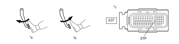
| *a | Brake pedal depressed | *b | Brake pedal released |
| *c | Front view of wire harness connector (to ECM) | - | - |
(b) Measure the voltage according to the value(s) in the table below.
Standard Voltage:
| Tester Connection | Condition | Specified Condition |
|---|---|---|
| A37-27 (STP) - Body ground | Brake pedal released | Below 1.5 V |
| Brake pedal depressed | 7.5 to 14 V |
HINT:
If there is a short in the STP terminal circuit, there may be a malfunction in the circuit of a connected ECU.
| OK | | REPLACE ECM |
| NG | | REPAIR OR REPLACE HARNESS OR CONNECTOR (STOP LIGHT SWITCH ASSEMBLY - ECM) |
 Actuator Supply Voltage "A" Stuck On (P06579E)
MONITOR DESCRIPTION The ECM monitors the output voltage to the throttle actuator. This self-check ensures that the ECM is functioning properly. The output voltage is usually 0 V when the engine switch ...
 Fuel Rail Pressure Sensor (Low) / Fuel Rail Pressure Sensor "B" Circuit Short to Ground (P107A11)
DESCRIPTION The fuel pressure sensor (for low pressure side) replaces the fuel pressure with electrical signals and outputs them to the ECM. The ECM controls the optimal fuel pressure for the operati ...
Other materials:
Lexus RX (RX 350L, RX450h) 2016-2026 Repair Manual > Sliding Roof System: Switch Failure (B2342)
DESCRIPTION This DTC is stored when the sliding roof ECU (sliding roof drive gear sub-assembly) detects that the sliding roof switch (map light assembly) is stuck for 30 seconds or more. DTC No. Detection Item DTC Detection Condition Trouble Area B2342 Switch Failure Sliding roof EC ...
Lexus RX (RX 350L, RX450h) 2016-2026 Repair Manual > Rear No. 2 Seat Outer Belt Assembly: Components
COMPONENTS ILLUSTRATION *A for RH Side *B for LH Side *1 FRONT DECK SIDE TRIM COVER *2 REAR DOOR INSIDE SCUFF PLATE *3 REAR DOOR SCUFF PLATE *4 REAR SEAT OUTER TRACK BRACKET COVER LH *5 REAR SEAT OUTER TRACK BRACKET COVER RH *6 REAR SEAT SIDE GARNISH ILLUST ...
Lexus RX (RX 350L, RX450h) 2016-{YEAR} Owners Manual
- For your information
- Pictorial index
- For safety and security
- Instrument cluster
- Operation of each component
- Driving
- Lexus Display Audio system
- Interior features
- Maintenance and care
- When trouble arises
- Vehicle specifications
- For owners
Lexus RX (RX 350L, RX450h) 2016-{YEAR} Repair Manual

0.0111