Lexus RX (RX 350L, RX450h) 2016-2026 Repair Manual: Removal
REMOVAL
CAUTION / NOTICE / HINT
The necessary procedures (adjustment, calibration, initialization, or registration) that must be performed after parts are removed and installed, or replaced during engine unit removal/installation are shown below.
Necessary Procedure After Parts Removed/Installed/Replaced| Replaced Part or Performed Procedure | Necessary Procedure | Effect/Inoperative Function when Necessary Procedure not Performed | Link |
|---|---|---|---|
|
*1: When performing learning using the Techstream.
Click here | |||
| Disconnect cable from negative battery terminal | Memorize steering angle neutral point | Lane Control System | |
| Pre-collision system | |||
| Intelligent clearance sonar system*1 | |||
| Lighting system (w/ Automatic Headlight Beam Level Control System) | | ||
| Parking assist monitor system | | ||
| Panoramic view monitor system | | ||
| Initialize back door lock | Power door lock control system | | |
| Reset back door close position | Power Back Door System (w/ Outside Door Control Switch) | | |
| Replacement of ECM | Vehicle Identification Number (VIN) registration | MIL comes on | |
| ECU Communication ID Registration (Immobiliser system) | Engine start function | | |
| Perform code registration (Immobiliser system) |
| | |
| Inspection After Repair |
| |
| Replacement of automatic transaxle assembly | Perform the following procedures in the order shown:
|
| for U881E Registration: for U881E Initialization: for U881F Registration: for U881F Initialization: |
| Replacement of ECM (If possible, read the transaxle compensation code from the previous ECM) | Perform the following procedures in the order shown:
| ||
| Replacement of ECM (If impossible, read the transaxle compensation code from the previous ECM) | Perform the following procedures in the order shown:
| ||
| Front wheel alignment adjustment | Calibration |
| |
| Suspension, tires, etc. (The vehicle height changes because of suspension or tire replacement) |
|
| |
| Rear television camera assembly optical axis (Back camera position setting) | Parking assist monitor system | for Initialization: for Calibration: | |
| Panoramic view monitor system | for Initialization: for Calibration: | |
| Initialize No. 1 headlight ECU sub-assembly LH | Lighting System (w/ Automatic Headlight Beam Level Control System) | | |
PROCEDURE
1. INSTALL ENGINE ASSEMBLY TO ENGINE STAND
Click here .gif)
2. REMOVE ENGINE HANGERS
Click here
3. REMOVE IGNITION COIL ASSEMBLY
Click here
4. REMOVE VACUUM PUMP ASSEMBLY
Click here
5. REMOVE ENGINE OIL LEVEL DIPSTICK GUIDE
Click here
6. REMOVE WIRE HARNESS CLAMP BRACKET
Click here
7. REMOVE RADIATOR PIPE CLAMP
Click here
8. REMOVE STUD BOLT
Click here
9. REMOVE CAMSHAFT TIMING OIL CONTROL SOLENOID ASSEMBLY (for Intake Side of Bank 1)
Click here
10. REMOVE CAMSHAFT TIMING OIL CONTROL SOLENOID ASSEMBLY (for Exhaust Side of Bank 1)
Click here
11. REMOVE CAMSHAFT TIMING OIL CONTROL SOLENOID ASSEMBLY (for Exhaust Side of Bank 2)
Click here
12. REMOVE CAMSHAFT TIMING OIL CONTROL SOLENOID ASSEMBLY (for Intake Side of Bank 2)
Click here
13. REMOVE VVT SENSOR (for Intake Side of Bank 1)
Click here
14. REMOVE VVT SENSOR (for Exhaust Side of Bank 1)
Click here
15. REMOVE VVT SENSOR (for Intake Side of Bank 2)
Click here
16. REMOVE VVT SENSOR (for Exhaust Side of Bank 2)
Click here
17. REMOVE CYLINDER HEAD COVER SUB-ASSEMBLY
Click here
18. REMOVE CYLINDER HEAD COVER SUB-ASSEMBLY LH
Click here
19. REMOVE SPARK PLUG TUBE GASKET
Click here
20. REMOVE TIMING CHAIN COVER PLATE
Click here
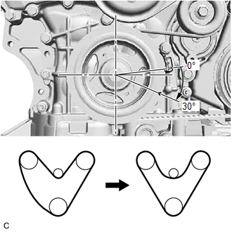
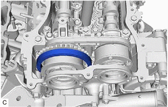
21. SET NO. 1 CYLINDER TO TDC (COMPRESSION)
| (a) Turn the crankshaft clockwise to align the timing mark (cutout) on the crankshaft pulley with the "0" timing mark on the timing chain cover assembly. |
|
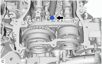
| (b) Check that the timing marks of the camshaft timing gear assemblies are aligned with the timing marks of the camshaft bearing caps as shown in the illustration. HINT: If the marks are not aligned, turn the crankshaft again to align the marks. |
|
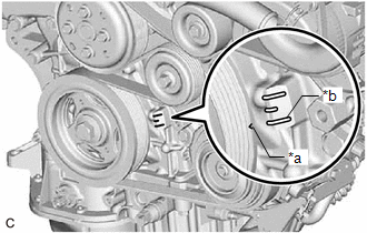
(c) Place paint marks on the timing marks and sprockets of each camshaft timing gear assembly and on the links of the chain sub-assembly.
HINT:
Be sure to place the paint marks on 2 links of the chain sub-assembly and on the sprockets of the camshaft timing gear assemblies at the locations of the timing marks of the camshaft timing gear assemblies.
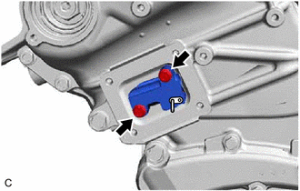
22. REMOVE NO. 1 CHAIN TENSIONER ASSEMBLY
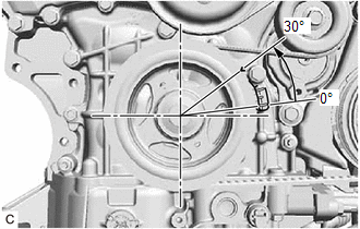
| (a) Turn the crankshaft approximately 30° counterclockwise so that there is some slack in the chain sub-assembly. HINT: This prevents the valves and pistons from interfering with each other. |
|
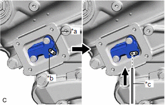
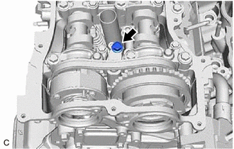
| (b) Align the hole in the lever of the No. 1 chain tensioner assembly with the hole in the tensioner body as shown in the illustration, and then insert a pin with a diameter of 1.0 mm (0.0394 in.) into the hole. NOTICE: Check that the pin is locked. |
|
| (c) Turn the crankshaft clockwise to align the timing mark (cutout) on the crankshaft pulley with the "0" timing mark on the timing chain cover assembly. |
|
| (d) Remove the 2 bolts and No. 1 chain tensioner assembly from the cylinder head sub-assembly. NOTICE: Do not drop the No. 1 chain tensioner assembly or bolts into the timing chain cover assembly. |
|
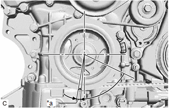
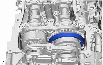
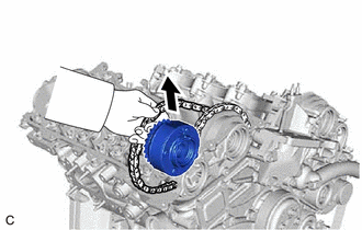
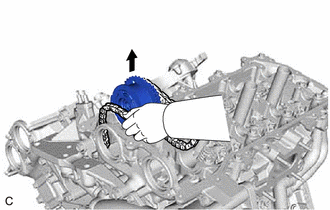
23. DISCONNECT CHAIN SUB-ASSEMBLY (for Bank 1)
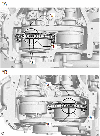
| (a) Turn the crankshaft clockwise until it is in the position shown in the illustration so that there is some slack in the chain sub-assembly between the banks. CAUTION: As the camshafts turn suddenly, do not touch the camshafts or camshaft timing gears. HINT: When turning the crankshaft, engine oil may spray out of the oil holes. |
|
| (b) Turn the crankshaft clockwise until it is in the position shown in the illustration so that the chain sub-assembly can be removed easily. HINT: When turning the crankshaft, engine oil may spray out of the oil holes. |
|
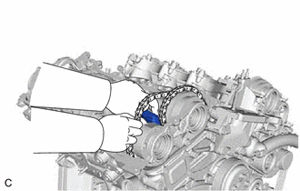
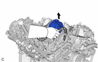
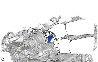
| (c) Remove the chain sub-assembly from the sprocket of the camshaft timing gear assembly and set it on the camshaft timing gear assembly. CAUTION: As the camshaft may turn suddenly and pinch your fingers when the chain sub-assembly is removed, pinch the chain sub-assembly and lift it upward to remove it from the sprocket. |
|
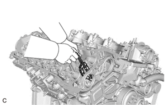
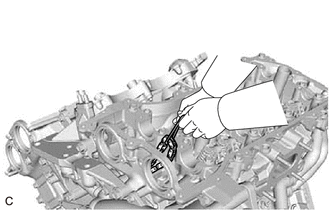
24. SEPARATE NO. 2 CHAIN TENSIONER ASSEMBLY
| (a) Remove the bolt of the No. 2 chain tensioner assembly. |
|
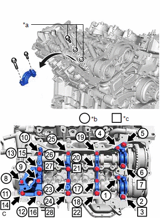
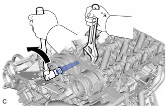
25. REMOVE CAMSHAFT TIMING GEAR BOLT (for Intake Side of Bank 1)
(a) Hold the hexagonal portion of the camshaft with a wrench and remove the camshaft timing gear bolt from the camshaft timing gear assembly.
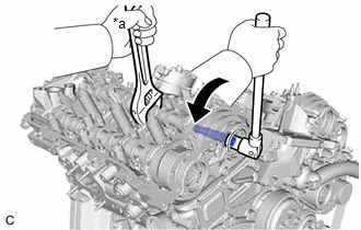
| *a | Hold |
.png) | Turn |
NOTICE:
- Be careful not to damage the camshaft, camshaft housing sub-assembly or spark plug tube with the wrench.
- If the camshaft timing gear bolt has been struck or dropped, replace it.
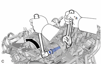
26. REMOVE CAMSHAFT TIMING GEAR BOLT (for Exhaust Side of Bank 1)
(a) Hold the hexagonal portion of the No. 2 camshaft with a wrench and remove the camshaft timing gear bolt from the camshaft timing exhaust gear assembly.
NOTICE:
- Be careful not to damage the camshaft, camshaft housing sub-assembly or spark plug tube with the wrench.
- If the camshaft timing gear bolt has been struck or dropped, replace it.
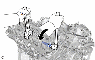
| *a | Hold |
| | Turn |
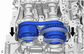
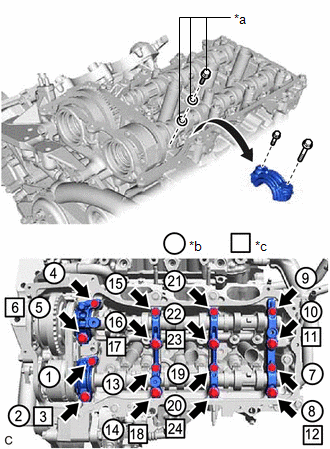
27. REMOVE CAMSHAFT BEARING CAP (for Bank 1)
| (a) Slide the camshaft timing gear assembly and camshaft timing exhaust gear assembly as shown in the illustration. |
|
| (b) Remove the bolts and camshaft bearing caps in the order shown in the illustration. Immediately after removing a camshaft bearing cap, install replacement bolts and washers in the order shown in the illustration. Torque: 10 N·m {102 kgf·cm, 7 ft·lbf} NOTICE:
HINT:
|
|
28. REMOVE NO. 2 CAMSHAFT
| (a) While lifting up the camshaft timing exhaust gear assembly, remove the No. 2 chain tensioner assembly. |
|
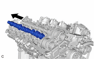
(b) Lift up the rear of the No. 2 camshaft so that it is at an angle.
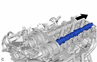
| (c) Pull the No. 2 camshaft as shown in the illustration to remove it from the camshaft timing exhaust gear assembly. |
|
29. REMOVE CAMSHAFT
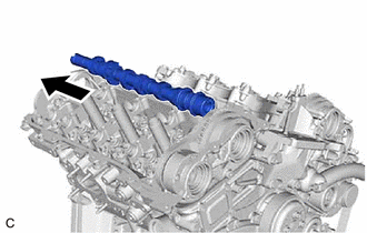
(a) Lift up the rear of the camshaft so that it is at an angle.
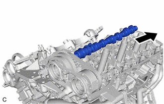
| (b) Pull the camshaft as shown in the illustration to remove it from the camshaft timing gear assembly. |
|
30. REMOVE CAMSHAFT TIMING EXHAUST GEAR ASSEMBLY (for Bank 1)
| (a) Remove the camshaft timing exhaust gear assembly. |
|
31. REMOVE CAMSHAFT TIMING GEAR ASSEMBLY (for Bank 1)
| (a) Remove the camshaft timing gear assembly and No. 2 chain sub-assembly. NOTICE: Do not drop the chain sub-assembly into the gap between the engine and timing chain cover assembly. |
|
| (b) Suspend the chain sub-assembly with a string or equivalent. |
|
32. DISCONNECT CHAIN SUB-ASSEMBLY (for Bank 2)
| (a) Turn the crankshaft counterclockwise to align the timing mark (cutout) on the crankshaft pulley with the "0" timing mark on the timing chain cover assembly. |
|
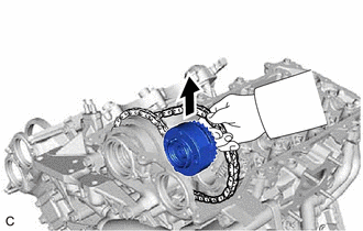
| (b) Remove the chain sub-assembly from the sprocket of the camshaft timing gear assembly and set it on the camshaft timing gear assembly. CAUTION: As the camshaft may turn suddenly and pinch your fingers when the chain sub-assembly is removed, pinch the chain sub-assembly and lift it upward to remove it from the sprocket. |
|
33. SEPARATE NO. 3 CHAIN TENSIONER ASSEMBLY
| (a) Remove the bolt of the No. 3 chain tensioner assembly. |
|
34. REMOVE CAMSHAFT TIMING GEAR BOLT (for Intake Side of Bank 2)
(a) Hold the hexagonal portion of the No. 3 camshaft sub-assembly with a wrench and remove the camshaft timing gear bolt from the camshaft timing gear assembly.
| *a | Hold |
| | Turn |
NOTICE:
- Be careful not to damage the No. 3 camshaft sub-assembly, camshaft housing sub-assembly LH or spark plug tube with the wrench.
- If the camshaft timing gear bolt has been struck or dropped, replace it.
35. REMOVE CAMSHAFT TIMING GEAR BOLT (for Exhaust Side of Bank 2)
(a) Hold the hexagonal portion of the No. 4 camshaft sub-assembly with a wrench and remove the camshaft timing gear bolt from the camshaft timing exhaust gear assembly.
| *a | Hold |
| | Turn |
NOTICE:
- Be careful not to damage the No. 4 camshaft sub-assembly, camshaft housing sub-assembly LH or spark plug tube with the wrench.
- If the camshaft timing gear bolt has been struck or dropped, replace it.
36. REMOVE CAMSHAFT BEARING CAP (for Bank 2)
| (a) Slide the camshaft timing gear assembly and camshaft timing exhaust gear assembly as shown in the illustration. |
|

| (b) Remove the bolts and camshaft bearing caps in the order shown in the illustration. Immediately after removing a camshaft bearing cap, install replacement bolts and washers in the order shown in the illustration. Torque: 10 N·m {102 kgf·cm, 7 ft·lbf} NOTICE:
HINT:
|
|
37. REMOVE NO. 4 CAMSHAFT SUB-ASSEMBLY
| (a) While lifting up the camshaft timing exhaust gear assembly, remove the No. 3 chain tensioner assembly. |
|
(b) Lift up the rear of the No. 4 camshaft sub-assembly so that it is at an angle.
| (c) Pull the No. 4 camshaft sub-assembly as shown in the illustration to remove it from the camshaft timing exhaust gear assembly. |
|
38. REMOVE NO. 3 CAMSHAFT SUB-ASSEMBLY
(a) Lift up the rear of the No. 3 camshaft sub-assembly so that it is at an angle.
| (b) Pull the No. 3 camshaft sub-assembly as shown in the illustration to remove it from the camshaft timing gear assembly. |
|
39. REMOVE CAMSHAFT TIMING EXHAUST GEAR ASSEMBLY (for Bank 2)
| (a) Remove the camshaft timing exhaust gear assembly. |
|
40. REMOVE CAMSHAFT TIMING GEAR ASSEMBLY (for Bank 2)
| (a) Remove the camshaft timing gear assembly and No. 2 chain sub-assembly. NOTICE: Do not drop the chain sub-assembly into the gap between the engine and timing chain cover assembly. |
|
| (b) Suspend the chain sub-assembly with a string or equivalent. |
|
 Components
COMPONENTS ILLUSTRATION *1 RADIATOR PIPE CLAMP *2 WIRE HARNESS CLAMP BRACKET *3 VACUUM PUMP ASSEMBLY *4 IGNITION COIL ASSEMBLY *5 ENGINE OIL LEVEL DIPSTICK GUIDE *6 ENGIN ...
 Installation
INSTALLATION PROCEDURE 1. SET NO. 1 CYLINDER TO TDC (COMPRESSION) (a) Confirm that the timing mark (cutout) on the crankshaft pulley is aligned with the "0" timing mark of the timing chain cover as ...
Other materials:
Lexus RX (RX 350L, RX450h) 2016-2026 Repair Manual > Fuel Pump (for Tmc Made): Installation
INSTALLATION PROCEDURE 1. INSTALL FUEL SUCTION TUBE WITH PUMP AND GAUGE ASSEMBLY (a) Install a new fuel suction tube set gasket to the fuel tank assembly. (b) Set the fuel suction tube with pump and gauge assembly to the fuel tank assembly. NOTICE: Be careful not to bend the arm of the fuel sende ...
Lexus RX (RX 350L, RX450h) 2016-2026 Repair Manual > Cooling Fan Motor: Removal
REMOVAL CAUTION / NOTICE / HINT The necessary procedures (adjustment, calibration, initialization or registration) that must be performed after parts are removed and installed, or replaced during cooling fan motor LH or cooling fan motor RH removal/installation are shown below. Necessary Procedures ...
Lexus RX (RX 350L, RX450h) 2016-{YEAR} Owners Manual
- For your information
- Pictorial index
- For safety and security
- Instrument cluster
- Operation of each component
- Driving
- Lexus Display Audio system
- Interior features
- Maintenance and care
- When trouble arises
- Vehicle specifications
- For owners
Lexus RX (RX 350L, RX450h) 2016-{YEAR} Repair Manual

0.0113