Lexus RX (RX 350L, RX450h) 2016-2026 Repair Manual: Removal
REMOVAL
CAUTION / NOTICE / HINT
The necessary procedures (adjustment, calibration, initialization, or registration) that must be performed after parts are removed and installed, or replaced during engine unit removal/installation are shown below.
Necessary Procedure After Parts Removed/Installed/Replaced| Replaced Part or Performed Procedure | Necessary Procedure | Effect/Inoperative Function when Necessary Procedure not Performed | Link |
|---|---|---|---|
|
*1: When performing learning using the Techstream.
Click here | |||
| Disconnect cable from negative battery terminal | Memorize steering angle neutral point | Lane Control System | |
| Pre-collision system | |||
| Intelligent clearance sonar system*1 | |||
| Lighting system (w/ Automatic Headlight Beam Level Control System) | | ||
| Parking assist monitor system | | ||
| Panoramic view monitor system | | ||
| Initialize back door lock | Power door lock control system | | |
| Reset back door close position | Power Back Door System (w/ Outside Door Control Switch) | | |
| Replacement of ECM | Vehicle Identification Number (VIN) registration | MIL comes on | |
| ECU Communication ID Registration (Immobiliser system) | Engine start function | | |
| Perform code registration (Immobiliser system) |
| | |
| Inspection After Repair |
| |
| Replacement of automatic transaxle assembly | Perform the following procedures in the order shown:
|
| for U881E Registration: for U881E Initialization: for U881F Registration: for U881F Initialization: |
| Replacement of ECM (If possible, read the transaxle compensation code from the previous ECM) | Perform the following procedures in the order shown:
| ||
| Replacement of ECM (If impossible, read the transaxle compensation code from the previous ECM) | Perform the following procedures in the order shown:
| ||
| Front wheel alignment adjustment | Calibration |
| |
| Suspension, tires, etc. (The vehicle height changes because of suspension or tire replacement) |
|
| |
| Rear television camera assembly optical axis (Back camera position setting) | Parking assist monitor system | for Initialization: for Calibration: | |
| Panoramic view monitor system | for Initialization: for Calibration: | |
| Initialize No. 1 headlight ECU sub-assembly LH | Lighting System (w/ Automatic Headlight Beam Level Control System) | | |
PROCEDURE
1. INSTALL ENGINE ASSEMBLY TO ENGINE STAND
Click here .gif)
2. REMOVE ENGINE HANGERS
Click here
3. REMOVE KNOCK CONTROL SENSOR
Click here
4. REMOVE IGNITION COIL ASSEMBLY
Click here
5. REMOVE VACUUM PUMP ASSEMBLY
Click here
6. REMOVE V-RIBBED BELT
Click here
7. REMOVE GENERATOR ASSEMBLY
-
for 180A Type:
Click here
-
for 150A Type:
Click here
8. REMOVE COMPRESSOR AND MAGNETIC CLUTCH
Click here
9. REMOVE NO. 2 IDLER PULLEY SUB-ASSEMBLY
Click here
10. REMOVE V-RIBBED BELT TENSIONER ASSEMBLY
Click here
11. REMOVE WATER PUMP PULLEY
Click here
12. REMOVE ENGINE OIL LEVEL DIPSTICK GUIDE
Click here
13. REMOVE NO. 5 CYLINDER BLOCK INSULATOR (w/ Oil Cooler)
Click here
14. REMOVE WIRE HARNESS CLAMP BRACKET
Click here
15. REMOVE RADIATOR PIPE CLAMP
Click here
16. REMOVE CRANKSHAFT PULLEY
Click here
17. REMOVE FRONT NO. 1 ENGINE MOUNTING BRACKET LH
Click here
18. DISCONNECT WATER BY-PASS HOSE
Click here
19. REMOVE WATER INLET WITH THERMOSTAT SUB-ASSEMBLY
Click here
20. REMOVE CAMSHAFT TIMING OIL CONTROL SOLENOID ASSEMBLY (for Intake Side of Bank 1)
Click here
21. REMOVE CAMSHAFT TIMING OIL CONTROL SOLENOID ASSEMBLY (for Exhaust Side of Bank 1)
Click here
22. REMOVE CAMSHAFT TIMING OIL CONTROL SOLENOID ASSEMBLY (for Exhaust Side of Bank 2)
Click here
23. REMOVE CAMSHAFT TIMING OIL CONTROL SOLENOID ASSEMBLY (for Intake Side of Bank 2)
Click here
24. REMOVE VVT SENSOR (for Intake Side of Bank 1)
Click here
25. REMOVE VVT SENSOR (for Exhaust Side of Bank 1)
Click here
26. REMOVE VVT SENSOR (for Intake Side of Bank 2)
Click here
27. REMOVE VVT SENSOR (for Exhaust Side of Bank 2)
Click here
28. REMOVE CRANKSHAFT POSITION SENSOR PROTECTOR
Click here
29. REMOVE SENSOR WIRE
Click here
30. REMOVE CYLINDER HEAD COVER SUB-ASSEMBLY
Click here
31. REMOVE CYLINDER HEAD COVER SUB-ASSEMBLY LH
Click here
32. REMOVE SPARK PLUG TUBE GASKET
Click here
33. REMOVE OIL COOLER ASSEMBLY (w/ Oil Cooler)
Click here
34. REMOVE OIL COOLER PIPE (w/ Oil Cooler)
Click here
35. REMOVE NO. 2 OIL PAN SUB-ASSEMBLY
Click here
36. REMOVE OIL STRAINER SUB-ASSEMBLY
Click here
37. REMOVE OIL PAN SUB-ASSEMBLY
| (a) Remove the 16 bolts and 2 nuts from the oil pan sub-assembly. NOTICE: Make sure to clean the bolts and stud bolts and check the threads for cracks or other damage. |
|
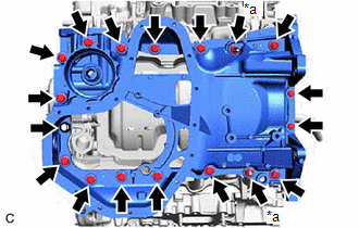
| (b) Remove the oil pan sub-assembly by prying between the oil pan sub-assembly and timing chain cover assembly or cylinder block sub-assembly with a screwdriver wrapped with protective tape. NOTICE: Be careful not to damage the contact surfaces of the cylinder block sub-assembly, timing chain cover assembly and oil pan sub-assembly. |
|
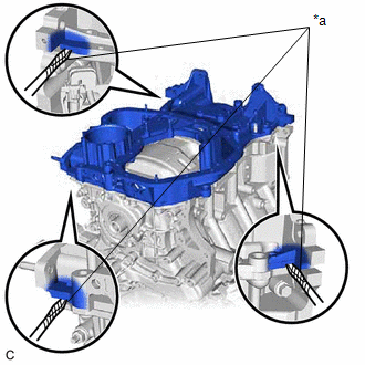
| (c) Remove the 2 oil pan gaskets from the timing chain cover assembly. |
|
38. REMOVE TIMING CHAIN COVER ASSEMBLY
Click here
39. REMOVE TIMING CHAIN CASE OIL SEAL
Click here
40. SET NO. 1 CYLINDER TO TDC (COMPRESSION)
Click here
41. REMOVE NO. 1 CHAIN TENSIONER ASSEMBLY
Click here
42. REMOVE CHAIN TENSIONER SLIPPER
Click here
43. REMOVE CHAIN SUB-ASSEMBLY
Click here
44. REMOVE CAMSHAFT TIMING GEAR ASSEMBLY, CAMSHAFT TIMING EXHAUST GEAR ASSEMBLY AND NO. 2 CHAIN SUB-ASSEMBLY (for Bank 1)
Click here
45. REMOVE NO. 2 CHAIN TENSIONER ASSEMBLY
Click here
46. REMOVE CAMSHAFT BEARING CAP (for Bank 1)
Click here
47. REMOVE CAMSHAFT
Click here
48. REMOVE NO. 2 CAMSHAFT
Click here
49. REMOVE CAMSHAFT HOUSING SUB-ASSEMBLY
Click here
50. REMOVE CAMSHAFT TIMING GEAR ASSEMBLY, CAMSHAFT TIMING EXHAUST GEAR ASSEMBLY AND NO. 2 CHAIN SUB-ASSEMBLY (for Bank 2)
Click here
51. REMOVE NO. 3 CHAIN TENSIONER ASSEMBLY
Click here
52. REMOVE CAMSHAFT BEARING CAP (for Bank 2)
Click here
53. REMOVE NO. 3 CAMSHAFT SUB-ASSEMBLY
Click here
54. REMOVE NO. 4 CAMSHAFT SUB-ASSEMBLY
Click here
55. REMOVE CAMSHAFT HOUSING SUB-ASSEMBLY LH
Click here
56. REMOVE SENSOR WIRE
Click here
57. REMOVE NO. 1 CHAIN VIBRATION DAMPER
Click here
58. REMOVE NO. 2 CHAIN VIBRATION DAMPER
Click here
59. REMOVE NO. 1 VALVE ROCKER ARM SUB-ASSEMBLY
Click here
60. REMOVE VALVE LASH ADJUSTER ASSEMBLY
Click here
61. REMOVE VALVE STEM CAP
Click here
62. REMOVE WATER OUTLET
Click here
63. REMOVE CYLINDER HEAD SUB-ASSEMBLY
Click here
64. REMOVE CYLINDER HEAD GASKET
(a) Remove the cylinder head gasket from the cylinder block sub-assembly.
65. REMOVE CYLINDER HEAD LH
Click here
66. REMOVE NO. 2 CYLINDER HEAD GASKET
(a) Remove the No. 2 cylinder head gasket from the cylinder block sub-assembly.
67. INSPECT CYLINDER HEAD SET BOLT
Click here
 Components
COMPONENTS ILLUSTRATION *A Type A *B Type B *C w/ Oil Cooler - - *1 IGNITION COIL ASSEMBLY *2 VACUUM PUMP ASSEMBLY *3 V-RIBBED BELT *4 GENERATOR ASSEMBLY *5 ...
 Installation
INSTALLATION PROCEDURE 1. INSTALL NO. 2 CYLINDER HEAD GASKET (a) Place a new No. 2 cylinder head gasket on the cylinder block sub-assembly as shown in the illustration. *a Lot No. Front o ...
Other materials:
Lexus RX (RX 350L, RX450h) 2016-2026 Repair Manual > Rear Combination Light Assembly (w/o Rear No. 2 Seat): Inspection
INSPECTION PROCEDURE 1. INSPECT REAR COMBINATION LIGHT ASSEMBLY LH (a) Apply battery voltage to the rear combination light assembly LH and check that the lights come on. OK: Condition Specified Condition Battery positive (+) → Terminal 1 (B) Battery negative (-) → Terminal 3 (E) T ...
Lexus RX (RX 350L, RX450h) 2016-2026 Repair Manual > Navigation System: Touch Panel Switch does not Function
CAUTION / NOTICE / HINT NOTICE: Depending on the parts that are replaced during vehicle inspection or maintenance, performing initialization, registration or calibration may be needed. Refer to Precaution for Navigation System. Click here PROCEDURE 1. CHECK MULTI-DISPLAY (a) Check if ther ...
Lexus RX (RX 350L, RX450h) 2016-{YEAR} Owners Manual
- For your information
- Pictorial index
- For safety and security
- Instrument cluster
- Operation of each component
- Driving
- Lexus Display Audio system
- Interior features
- Maintenance and care
- When trouble arises
- Vehicle specifications
- For owners
Lexus RX (RX 350L, RX450h) 2016-{YEAR} Repair Manual

0.0112