Lexus RX (RX 350L, RX450h) 2016-2026 Repair Manual: Terminals Of Ecm
TERMINALS OF ECM
CHECK ECM
HINT:
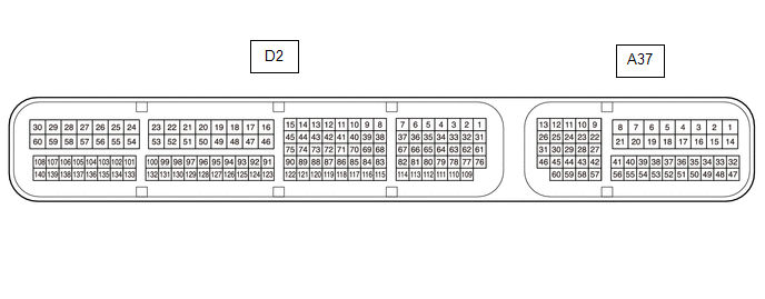
The standard normal voltage between each pair of ECM terminals is shown in the table below. The appropriate conditions for checking each pair of terminals are also indicated. The result of checks should be compared with the standard normal voltage for that pair of terminals, displayed in the Specified Condition column. The illustration above can be used as a reference to identify the ECM terminal locations.
| Terminal No. (Symbol) | Wiring Color | Terminal Description | Condition | Specified Condition |
|---|---|---|---|---|
| D2-53 (E1) - Body ground | BR - Body ground | Ground | Always | Below 1 Ω |
| A37-1 (BATT) - D2-53 (E1) | G - BR | Battery (for measuring battery voltage and for ECM memory) | Always | 11 to 14 V |
| D2-135 (LIN) - Body ground | B - Body ground | LIN communication line | Engine switch off (while LIN communication stopped) | 10 kΩ or higher |
 Problem Symptoms Table
PROBLEM SYMPTOMS TABLE HINT:
Use the table below to help determine the cause of problem symptoms. If multiple suspected areas are listed, the potential causes of the symptoms are listed in order of ...
 Diagnosis System
DIAGNOSIS SYSTEM DLC3 (Data Link Connector 3) (a) Check the DLC3. Click here BATTERY VOLTAGE Standard Voltage: 11 to 14 V If the voltage is below 11 V, replace or recharge the battery. ...
Other materials:
Lexus RX (RX 350L, RX450h) 2016-2026 Repair Manual > Electrical Key Oscillator (for Front Floor): Installation
INSTALLATION PROCEDURE 1. INSTALL NO. 1 INDOOR ELECTRICAL KEY ANTENNA ASSEMBLY (a) Engage the clamp to install the No. 1 indoor electrical key antenna assembly as shown in the illustration. NOTICE: Be careful when installing the No. 1 indoor electrical key antenna assembly. If the No. 1 indoor elect ...
Lexus RX (RX 350L, RX450h) 2016-2026 Repair Manual > Instrument Panel Speaker: Inspection
INSPECTION PROCEDURE 1. INSPECT FRONT NO. 2 SPEAKER ASSEMBLY (for 9 Speakers) (a) With the speaker installed, check that there is no looseness or other abnormalities. (b) Check that there is no foreign matter in the speaker, no tears on the speaker cone or other abnormalities. (c) Measure the res ...
Lexus RX (RX 350L, RX450h) 2016-{YEAR} Owners Manual
- For your information
- Pictorial index
- For safety and security
- Instrument cluster
- Operation of each component
- Driving
- Lexus Display Audio system
- Interior features
- Maintenance and care
- When trouble arises
- Vehicle specifications
- For owners
Lexus RX (RX 350L, RX450h) 2016-{YEAR} Repair Manual

0.0177