Lexus RX (RX 350L, RX450h) 2016-2026 Repair Manual: Lost Communication with "Seat Control Module A" (U0208)
DESCRIPTION
| DTC No. | Detection Item | DTC Detection Condition | Trouble Area | Note |
|---|---|---|---|---|
| U0208 | Lost Communication with "Seat Control Module A" | No communication from the position control ECU and switch assembly LH continues. |
| HINT: The main body ECU (multiplex network body ECU) stores DTCs when it detects a communication stop or network communication error for ECUs connected to sub bus 1. |
HINT:
This diagnostic procedure is for when DTC U0208 is output by the main body ECU (multiplex network body ECU) (Techstream display: Main Body).
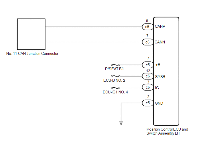
WIRING DIAGRAM
CAUTION / NOTICE / HINT
NOTICE:
- Before measuring the resistance of the CAN bus, turn the engine switch off and leave the vehicle for 1 minute or more without operating the key or any switches, or opening or closing the doors. After that, disconnect the cable from the negative (-) battery terminal and leave the vehicle for 1 minute or more before measuring the resistance.
-
After turning the engine switch off, waiting time may be required before disconnecting the cable from the negative (-) battery terminal. Therefore, make sure to read the disconnecting the cable from the negative (-) battery terminal notices before proceeding with work.
Click here
.gif)
-
Because the order of diagnosis is important to allow correct diagnosis, make sure to begin troubleshooting using How to Proceed with Troubleshooting when CAN communication system related DTCs are output.
Click here
- After performing repairs, perform the DTC check procedure and confirm that the DTCs are not output again.
- DTC check procedure: Turn the engine switch on (IG) and wait for at least 20 seconds.
-
After the repair, perform the CAN bus check and check that all the ECUs and sensors connected to the CAN communication system are displayed.
Click here
- Inspect the fuses for circuits related to this system before performing the following procedure.
HINT:
- Operating the engine switch, any other switches or a door triggers related ECU and sensor communication on the CAN. This communication will cause the resistance value to change.
- Even after DTCs are cleared, if a DTC is stored again after driving the vehicle for a while, the malfunction may be occurring due to vibration of the vehicle. In such a case, wiggling the ECUs or wire harness while performing the inspection below may help determine the cause of the malfunction.
PROCEDURE
| 1. | RECONFIRM DTC OUTPUT |
(a) Reconfirm DTCs.
HINT:
If DTC U1002 is output from Main Body of the main body ECU (multiplex network body ECU), this indicates a sub bus 1 malfunction. Troubleshoot for DTC U1002 and check for malfunctions in sub bus 1.
Body Electrical > Main Body > Trouble Codes| Result | Proceed to |
|---|---|
| DTC U1002 is not output from the main body ECU (multiplex network body ECU) (Techstream display: Main Body) | A |
| DTC U1002 is output from the main body ECU (multiplex network body ECU) (Techstream display: Main Body) | B |
| B | .gif) | GO TO DIAGNOSTIC PROCEDURE INDICATED BY OUTPUT DTC |
|
.gif)
| 2. | CHECK FOR OPEN IN SUB BUS 1 LINES (POSITION CONTROL ECU AND SWITCH ASSEMBLY LH BRANCH LINE) |
(a) Disconnect the cable from the negative (-) battery terminal.
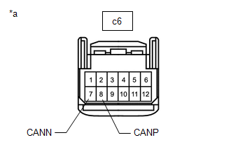
| (b) Disconnect the c6 position control ECU and switch assembly LH connector. |
|
(c) Measure the resistance according to the value(s) in the table below.
Standard Resistance:
| Tester Connection | Condition | Specified Condition |
|---|---|---|
| c6-8 (CANP) - c6-7 (CANN) | Cable disconnected from negative (-) battery terminal | 54 to 69 Ω |
| NG | | REPAIR OR REPLACE CAN BRANCH LINES OR CONNECTOR (POSITION CONTROL ECU AND SWITCH ASSEMBLY LH) |
|
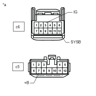
| 3. | CHECK HARNESS AND CONNECTOR (POWER SOURCE CIRCUIT) |
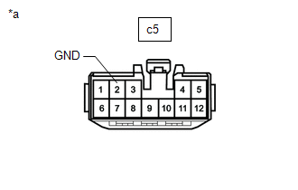
| (a) Disconnect the c5 position control ECU and switch assembly LH connector. |
|
(b) Measure the resistance according to the value(s) in the table below.
Standard Resistance:
| Tester Connection | Condition | Specified Condition |
|---|---|---|
| c5-2 (GND) - Body ground | Cable disconnected from negative (-) battery terminal | Below 1 Ω |
(c) Reconnect the cable to the negative (-) battery terminal.
| (d) Measure the voltage according to the value(s) in the table below. Standard Voltage:
|
|
| OK | | REPLACE POSITION CONTROL ECU AND SWITCH ASSEMBLY LH |
| NG | | REPAIR OR REPLACE HARNESS OR CONNECTOR (POWER SOURCE CIRCUIT) |
 Lost Communication with "Door Control Module A" (U0199)
DESCRIPTION DTC No. Detection Item DTC Detection Condition Trouble Area Note U0199 Lost Communication with "Door Control Module A" No communication from the outer mirror control ECU ...
 Lost Communication with Rear Gate Module (U0230)
DESCRIPTION DTC No. Detection Item DTC Detection Condition Trouble Area Note U0230 Lost Communication with Rear Gate Module No communication from the multiplex network door ECU cont ...
Other materials:
Lexus RX (RX 350L, RX450h) 2016-2026 Repair Manual > Seat: Seat Heater Control(for Front Side)
ComponentsCOMPONENTS ILLUSTRATION *1 SEAT HEATER CONTROL SUB-ASSEMBLY - - RemovalREMOVAL CAUTION / NOTICE / HINT The necessary procedures (adjustment, calibration, initialization or registration) that must be performed after parts are removed and installed, or replaced during seat heate ...
Lexus RX (RX 350L, RX450h) 2016-2026 Repair Manual > Blind Spot Monitor System: Blind Spot Monitor Master Module Beam Axis Inspection Incomplete (C1ABB)
DESCRIPTION This DTC is stored when a beam axis adjustment has not been performed for the blind spot monitor sensor LH. HINT: This DTC is always stored after replacing a blind spot monitor sensor. The purpose of this DTC is to ensure that a beam axis adjustment is performed. Completing the beam axis ...
Lexus RX (RX 350L, RX450h) 2016-{YEAR} Owners Manual
- For your information
- Pictorial index
- For safety and security
- Instrument cluster
- Operation of each component
- Driving
- Lexus Display Audio system
- Interior features
- Maintenance and care
- When trouble arises
- Vehicle specifications
- For owners
Lexus RX (RX 350L, RX450h) 2016-{YEAR} Repair Manual

0.0118