Lexus RX (RX 350L, RX450h) 2016-2026 Repair Manual: Terminals Of Ecu
TERMINALS OF ECU
CHECK POWER STEERING ECU ASSEMBLY
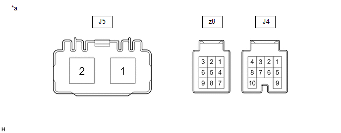
| *a | Component without harness connected (Power Steering ECU Assembly) | - | - |
(a) Measure the voltage and resistance according to the value(s) in the table below.
NOTICE:
When the EPS warning light is illuminated due to a malfunction, the fail-safe function may cause the voltage of the power steering ECU assembly terminals to become 0 V.
| Terminal No. (Symbol) | Wiring Color | Terminal Description | Condition | Specified Condition |
|---|---|---|---|---|
| J4-1 (IG) - Body ground | P - Body ground | IG power source | Engine switch on (IG) | 8 to 16 V |
| J4-7 (CANH) - J4-8 (CANL) | GR - W | CAN communication line | Engine switch off | 54 to 69 Ω |
| z8-1 (TRQ2) - z8-2 (TRQG2) | Y - G | Torque sensor 2 signal | Engine running and steering wheel not being turned (without load) | 2.3 to 2.7 V |
| Engine running and steering wheel being turned to the right with vehicle stopped | 1.2 to 2.5 V | |||
| Engine running and steering wheel being turned to the left with vehicle stopped | 2.5 to 3.8 V | |||
| z8-2 (TRQG2) - Body ground | G - Body ground | Torque sensor 2 ground | Always | Below 1 Ω |
| z8-3 (TRQV2) - z8-2 (TRQG2) | L - G | Torque sensor 2 voltage source | Engine switch on (IG) | 4.5 to 5.5 V |
| z8-7 (TRQV1) - z8-8 (TRQG1) | R - B | Torque sensor 1 voltage source | Engine switch on (IG) | 4.5 to 5.5 V |
| z8-8 (TRQG1) - Body ground | B - Body ground | Torque sensor 1 ground | Always | Below 1 Ω |
| z8-9 (TRQ1) - z8-8 (TRQG1) | W - B | Torque sensor 1 signal | Engine running and steering wheel not being turned (without load) | 2.3 to 2.7 V |
| Engine running and steering wheel being turned to the right with vehicle stopped | 2.5 to 3.8 V | |||
| Engine running and steering wheel being turned to the left with vehicle stopped | 1.2 to 2.5 V | |||
| J5-1 (PIG) - Body ground | W - Body ground | Power source | Always | 9 to 16 V |
| J5-2 (PGND) - Body ground | B - Body ground | Power ground | Always | Below 1 Ω |
If the result is not as specified, the ECU may be malfunctioning.
 System Diagram
SYSTEM DIAGRAM ...
 Lost Communication with ECM / PCM "A" (U0100,U0129,U023A)
DESCRIPTION The power steering ECU assembly receives signals from the ECM, skid control ECU (brake actuator assembly) and forward recognition camera (w/ forward recognition camera system) via CAN comm ...
Other materials:
Lexus RX (RX 350L, RX450h) 2016-2026 Repair Manual > Accelerator Pedal: Removal
REMOVAL PROCEDURE 1. REMOVE FRONT DOOR SCUFF PLATE LH Click here 2. REMOVE COWL SIDE TRIM BOARD Click here 3. REMOVE NO. 1 INSTRUMENT PANEL UNDER COVER SUB-ASSEMBLY Click here 4. REMOVE ACCELERATOR PEDAL SENSOR ASSEMBLY NOTICE:
Avoid physical shock to the accelerator pedal sensor a ...
Lexus RX (RX 350L, RX450h) 2016-2026 Repair Manual > Power Back Door Control Switch: Inspection
INSPECTION PROCEDURE 1. INSPECT POWER BACK DOOR SWITCH (INTEGRATION CONTROL AND PANEL ASSEMBLY) (a) Check the operation of the power back door switch (integration control and panel assembly). (1) Measure the resistance according to the value(s) in the table below. Standard Resistance: Tester ...
Lexus RX (RX 350L, RX450h) 2016-{YEAR} Owners Manual
- For your information
- Pictorial index
- For safety and security
- Instrument cluster
- Operation of each component
- Driving
- Lexus Display Audio system
- Interior features
- Maintenance and care
- When trouble arises
- Vehicle specifications
- For owners
Lexus RX (RX 350L, RX450h) 2016-{YEAR} Repair Manual

0.0098