Lexus RX (RX 350L, RX450h) 2016-2026 Repair Manual: Telescopic Position Sensor or Telescopic Motor Circuit Malfunction (B2611)
DESCRIPTION
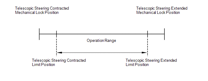
The telescopic motor is operated by the power source voltage supplied from the multiplex tilt and telescopic ECU and slides the steering column forward and backward. The telescopic position sensor (Hall IC) in the telescopic motor detects the sliding position of the steering column in the forward and backward directions and sends a signal to the multiplex tilt and telescopic ECU based on that sliding amount.
HINT:
Limit positions can be confirmed on the Techstream.
| DTC No. | Detection Item | DTC Detection Condition | Trouble Area |
|---|---|---|---|
| B2611 | Telescopic Position Sensor or Telescopic Motor Circuit Malfunction | Telescopic operation stops within the operation range while operating. |
|
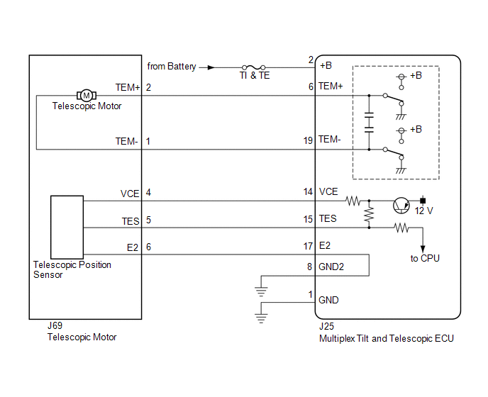
WIRING DIAGRAM
CAUTION / NOTICE / HINT
NOTICE:
If the electric power steering column sub-assembly (tilt steering gear assembly w/ motor) has been replaced, perform torque sensor zero point calibration.
Click here .gif)
HINT:
Inspect the fuses for circuits related to this system before performing the following inspection procedure.
PROCEDURE
| 1. | PERFORM ACTIVE TEST USING TECHSTREAM (TILT OPERATION) |
| (a) Turn the engine switch off. |
|
(b) Connect the Techstream to the DLC3.
(c) Turn the engine switch on (IG).
(d) Turn the Techstream on.
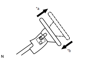
(e) Check that the steering column contracts and extends.
(f) Enter the following menus: Body Electrical / Tilt & Telescopic / Active Test.
Body Electrical > Tilt&Telescopic > Active Test| Tester Display | Measurement Item | Control Range | Diagnostic Note |
|---|---|---|---|
| Telesco Operation | Telesco Operation | LONG/SHORT | - |
| Tester Display |
|---|
| Telesco Operation |
OK:
The steering column contracts and extends.
| NG | .gif) | GO TO STEP 6 |
|
.gif)
| 2. | CHECK HARNESS AND CONNECTOR (MULTIPLEX TILT AND TELESCOPIC ECU - TELESCOPIC POSITION SENSOR) |
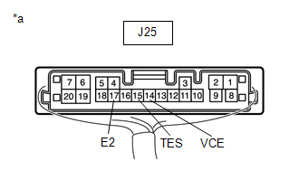
(a) Disconnect the J25 multiplex tilt and telescopic ECU connector.
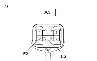
(b) Disconnect the J69 telescopic motor connector.
(c) Measure the resistance according to the value(s) in the table below.
Standard Resistance:
| Tester Connection | Condition | Specified Condition |
|---|---|---|
| J25-14 (VCE) - J69-4 (VCE) | Always | Below 1 Ω |
| J25-15 (TES) - J69-5 (TES) | Always | Below 1 Ω |
| J25-17 (E2) - J69-6 (E2) | Always | Below 1 Ω |
| J25-14 (VCE) or J69-4 (VCE) - Body ground | Always | 10 kΩ or higher |
| J25-15 (TES) or J69-5 (TES) - Body ground | Always | 10 kΩ or higher |
| J25-17 (E2) or J69-6 (E2) - Body ground | Always | 10 kΩ or higher |
| NG | | REPAIR OR REPLACE HARNESS OR CONNECTOR |
|
| 3. | CHECK HARNESS AND CONNECTOR (MULTIPLEX TILT AND TELESCOPIC ECU - BODY GROUND) |
| (a) Disconnect the J25 multiplex tilt and telescopic ECU connector. |
|
(b) Measure the resistance according to the value(s) in the table below.
Standard Resistance:
| Tester Connection | Condition | Specified Condition |
|---|---|---|
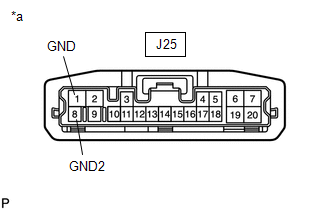
| J25-1 (GND) - Body ground | Always | Below 1 Ω |
| J25-8 (GND2) - Body ground | Always | Below 1 Ω |
| NG | | REPAIR OR REPLACE HARNESS OR CONNECTOR |
|
| 4. | CHECK MULTIPLEX TILT AND TELESCOPIC ECU (VCE, TES TERMINAL VOLTAGE) |
| (a) Disconnect the J69 telescopic motor connector. |
|
(b) Reconnect the J25 multiplex tilt and telescopic ECU connector.
(c) Measure the voltage according to the value(s) in the table below.
Standard Voltage:
| Tester Connection | Condition | Specified Condition |
|---|---|---|
| J25-14 (VCE) - J25-17 (E2) | Engine switch on (IG) | 8 to 14 V |
| J25-15 (TES) - J25-17 (E2) | Engine switch on (IG) | 8 to 14 V |
| NG | | REPLACE MULTIPLEX TILT AND TELESCOPIC ECU |
|
| 5. | CHECK TELESCOPIC POSITION SENSOR |
| (a) Reconnect the J25 multiplex tilt and telescopic ECU connector. |
|
(b) Reconnect the J69 telescopic motor connector.
(c) Measure the voltage according to the value(s) in the table below.
Standard Voltage:
| Tester Connection | Condition | Specified Condition |
|---|---|---|
| J69-5 (TES) - J69-6 (E2) | Steering column contracting or extending | Pulse generation High: 8 to 14 V Low: Below 1 V |
| OK | | REPLACE MULTIPLEX TILT AND TELESCOPIC ECU |
| NG | | REPLACE ELECTRIC POWER STEERING COLUMN SUB-ASSEMBLY (TILT STEERING GEAR ASSEMBLY W/ MOTOR) |
| 6. | CHECK HARNESS AND CONNECTOR (MULTIPLEX TILT AND TELESCOPIC ECU - BATTERY) |
(a) Disconnect the J25 multiplex tilt and telescopic ECU connector.
| (b) Measure the voltage according to the value(s) in the table below. Standard Voltage:
|
|
.png)
| NG | | REPAIR OR REPLACE HARNESS OR CONNECTOR |
|
| 7. | CHECK HARNESS AND CONNECTOR (MULTIPLEX TILT AND TELESCOPIC ECU - BODY GROUND) |
| (a) Disconnect the J25 multiplex tilt and telescopic ECU connector. |
|
(b) Measure the resistance according to the value(s) in the table below.
Standard Resistance:
| Tester Connection | Condition | Specified Condition |
|---|---|---|
| J25-1 (GND) - Body ground | Always | Below 1 Ω |
| J25-8 (GND2) - Body ground | Always | Below 1 Ω |
| NG | | REPAIR OR REPLACE HARNESS OR CONNECTOR |
|
| 8. | CHECK HARNESS AND CONNECTOR (MULTIPLEX TILT AND TELESCOPIC ECU - TELESCOPIC MOTOR) |
(a) Disconnect the J25 multiplex tilt and telescopic ECU connector.
(b) Disconnect the J69 telescopic motor connector.
(c) Measure the resistance according to the value(s) in the table below.
Standard Resistance:
| Tester Connection | Condition | Specified Condition |
|---|---|---|
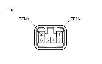
| J25-6 (TEM+) - J69-2 (TEM+) | Always | Below 1 Ω |
| J25-19 (TEM-) - J69-1 (TEM-) | Always | Below 1 Ω |
| J25-6 (TEM+) or J69-2 (TEM+) - Body ground | Always | 10 kΩ or higher |
| J25-19 (TEM-) or J69-1 (TEM-) - Body ground | Always | 10 kΩ or higher |
| NG | | REPAIR OR REPLACE HARNESS OR CONNECTOR |
|
| 9. | CHECK TELESCOPIC MOTOR |
| (a) Apply 12 V battery voltage to the telescopic motor connector. Then check the steering column telescopic operation. OK:
|
|
| OK | | REPLACE MULTIPLEX TILT AND TELESCOPIC ECU |
| NG | | REPLACE ELECTRIC POWER STEERING COLUMN SUB-ASSEMBLY (TILT STEERING GEAR ASSEMBLY W/ MOTOR) |
 Tilt Position Sensor or Tilt Motor Circuit Malfunction (B2610)
DESCRIPTION The tilt motor is operated by the power source voltage supplied from the multiplex tilt and telescopic ECU and tilts the steering column up and down. The tilt position sensor (Hall IC) in ...
 ECU Power Source Circuit Malfunction (B2620)
DESCRIPTION The ECU power source circuit supplies positive (+) voltage to the multiplex tilt and telescopic ECU. DTC No. Detection Item DTC Detection Condition Trouble Area B2620 ECU Po ...
Other materials:
Lexus RX (RX 350L, RX450h) 2016-2026 Repair Manual > Intuitive Parking Assist System (w/ Intelligent Clearance Sonar System): Customize Parameters
CUSTOMIZE PARAMETERS CUSTOMIZE INTUITIVE PARKING ASSIST SYSTEM (a) Customizing with the Techstream. NOTICE:
When the customer requests a change in a function, first make sure that the function can be customized.
Be sure to make a note of the current settings before customizing.
When troublesh ...
Lexus RX (RX 350L, RX450h) 2016-2026 Repair Manual > Power Steering System: Drive Mode Select Switch Circuit
DESCRIPTION The electronic throttle and the EPS character change by the operation of the drive mode select switch (combination switch assembly). WIRING DIAGRAM PROCEDURE 1. CHECK THE PROBLEM SYMPTOMS (a) Check each symptom by checking the suspected areas in the table below. Result Pro ...
Lexus RX (RX 350L, RX450h) 2016-{YEAR} Owners Manual
- For your information
- Pictorial index
- For safety and security
- Instrument cluster
- Operation of each component
- Driving
- Lexus Display Audio system
- Interior features
- Maintenance and care
- When trouble arises
- Vehicle specifications
- For owners
Lexus RX (RX 350L, RX450h) 2016-{YEAR} Repair Manual

0.0117