Lexus RX (RX 350L, RX450h) 2016-2026 Repair Manual: Power Source Control ECU Malfunction (B2782)
DESCRIPTION
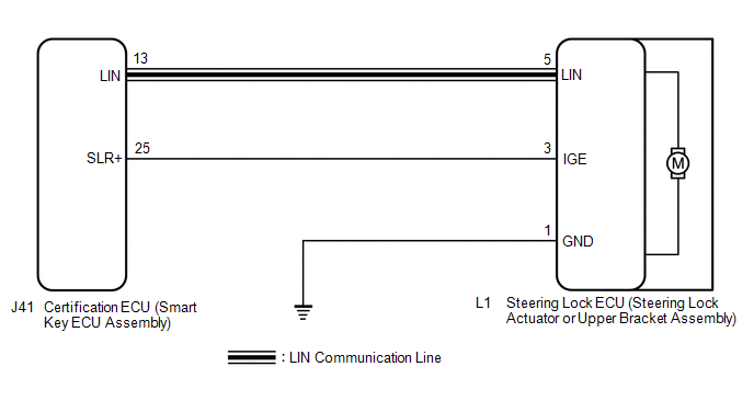
The certification ECU (smart key ECU assembly) has a power source mode switching function.
This DTC is stored when the IGE input (the steering lock motor activation permission signal) sent directly from the certification ECU (smart key ECU assembly) to the steering lock ECU (steering lock actuator or upper bracket assembly) is determined to be abnormal.
HINT:
The steering lock ECU (steering lock actuator or upper bracket assembly) is not connected to the CAN communication system. However, the steering lock ECU (steering lock actuator or upper bracket assembly) is connected to the certification ECU (smart key ECU assembly) via LIN communication and communicates with other components via CAN communication through the certification ECU (smart key ECU assembly).
| DTC No. | Detection Item | DTC Detection Condition | Trouble Area | Note |
|---|---|---|---|---|
| B2782 | Power Source Control ECU Malfunction | Either of the following conditions is met (1-trip detection logic (Only output while a malfunction is present and the engine switch is on (IG).)):
HINT: If the power supply signal from the LIN communication line does not match the power supply signal from the direct line, the system is determined to be malfunctioning. |
| DTC Output Confirmation Operation: Perform a steering lock/unlock operation. (The steering locks when a door is opened with the shift lever in P and the engine switch off. The steering unlocks when the engine switch is turned on (ACC) or on (IG) while carrying the key.) |
| Vehicle Condition when Malfunction Detected | Fail-safe Function when Malfunction Detected |
|---|---|
| The steering cannot be locked or unlocked. For this reason, the engine cannot be started. | Prohibits the engine from being started (the engine does not crank). |
| DTC No. | Data List Item | Active Test Item |
|---|---|---|
| B2782 | - | - |
WIRING DIAGRAM
CAUTION / NOTICE / HINT
NOTICE:
- When using the Techstream with the engine switch off, connect the Techstream to the vehicle and turn a courtesy light switch on and off at intervals of 1.5 seconds or less until communication between the Techstream and the vehicle begins. Then select the Model Code "KEY REGIST" under manual mode and enter the following menus: Body Electrical / Smart Access. While using the Techstream, periodically turn a courtesy light switch on and off at intervals of 1.5 seconds or less to maintain communication between the Techstream and the vehicle.
-
The steering lock system uses LIN communication. First perform the inspections in "How to Proceed with Troubleshooting" to confirm that there are no communication malfunctions before proceeding with troubleshooting.
Click here
.gif)
-
When disconnecting the cable from the negative (-) battery terminal, some systems need to be initialized after the cable is reconnected.
Click here
-
After performing repairs, perform the DTC output confirmation operation, and then confirm that no DTCs are output again.
Click here
-
When replacing the steering lock ECU (steering lock actuator or upper bracket assembly) or certification ECU (smart key ECU assembly), registration must be performed.
Click here
PROCEDURE
| 1. | INSPECT STEERING LOCK ECU (STEERING LOCK ACTUATOR OR UPPER BRACKET ASSEMBLY) |
(a) Make sure that there is no looseness at the locking part and the connecting part of the connector.
(b) Disconnect the L1 steering lock ECU (steering lock actuator or upper bracket assembly) connector.
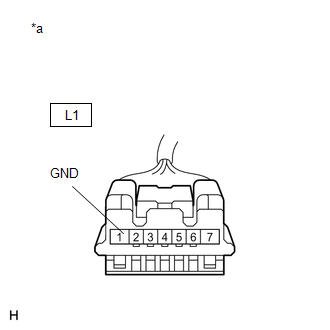
| (c) Measure the resistance according to the value(s) in the table below. Standard Resistance:
|
|
(d) Reconnect the L1 steering lock ECU (steering lock actuator or upper bracket assembly) connector.
(e) Move the shift lever to P and turn the engine switch off.
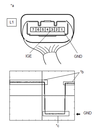
| (f) Check the signal waveform according to the condition(s) in the table below. Standard Frequency:
HINT:
|
|
| NG | .gif) | GO TO STEP 4 |
|
.gif)
| 2. | CLEAR DTC AND DATA LIST MALFUNCTION RECORD |
(a) Clear the DTCs.
Click here
(b) Disconnect the cable from the negative (-) battery terminal, wait for 30 seconds or more, and then reconnect the cable to the negative (-) battery terminal to clear the record of malfunctions stored in the Data List.
CAUTION:
After turning the engine switch off, waiting time may be required before disconnecting the cable from the battery terminal. Therefore, make sure to read the disconnecting the cable from the battery terminal notices before proceeding with work.
Click here
|
| 3. | CHECK DTC |
(a) Perform the DTC output confirmation operation.
(b) Check if DTC B2782 is output.
Click here
| Result | Proceed to |
|---|---|
| DTC B2782 is not output. | A |
| DTC B2782 is output. | B |
| A | | SYSTEM RETURNED TO NORMAL (DTC STORED DUE TO BAD CONNECTION, BUT SYSTEM RETURNED TO NORMAL BY RECONNECTING CONNECTOR) |
| B | | REPLACE STEERING LOCK ECU (STEERING LOCK ACTUATOR OR UPPER BRACKET ASSEMBLY) |
| 4. | CHECK HARNESS AND CONNECTOR (STEERING LOCK ECU (STEERING LOCK ACTUATOR OR UPPER BRACKET ASSEMBLY) - CERTIFICATION ECU (SMART KEY ECU ASSEMBLY)) |
(a) Make sure that there is no looseness at the locking part and the connecting part of the connectors.
(b) Disconnect the L1 steering lock ECU (steering lock actuator or upper bracket assembly) connector.
(c) Disconnect the J41 certification ECU (smart key ECU assembly) connector.
(d) Check for deformation and corrosion of the connector case and terminals.
OK:
There is no deformation or corrosion of the connector case or terminals.
(e) Measure the resistance according to the value(s) in the table below.
Standard Resistance:
| Tester Connection | Condition | Specified Condition |
|---|---|---|
| L1-3 (IGE) - J41-25 (SLR+) | Always | Below 1 Ω |
| L1-3 (IGE) or J41-25 (SLR+) - Body ground | Always | 10 kΩ or higher |
| OK | | REPLACE CERTIFICATION ECU (SMART KEY ECU ASSEMBLY) |
| NG | | REPAIR OR REPLACE HARNESS OR CONNECTOR |
 Open / Short in Steering Lock ECU (B2781)
DESCRIPTION The steering lock ECU and steering lock motor are built into the steering lock actuator or upper bracket assembly. The steering lock ECU (steering lock actuator or upper bracket assembly) ...
 IG2 Signal Malfunction (B2788)
DESCRIPTION This DTC is stored when the steering lock ECU (steering lock actuator or upper bracket assembly) detects an IG2 power supply malfunction. HINT: The steering lock ECU (steering lock actuato ...
Other materials:
Lexus RX (RX 350L, RX450h) 2016-2026 Repair Manual > Fuel Main Valve: Removal
REMOVAL CAUTION / NOTICE / HINT The necessary procedures (adjustment, calibration, initialization or registration) that must be performed after parts are removed and installed, or replaced during fuel main valve assembly removal/installation are shown below. Necessary Procedures After Parts Removed/ ...
Lexus RX (RX 350L, RX450h) 2016-2026 Repair Manual > Air Conditioning System: Customize Parameters
CUSTOMIZE PARAMETERS CUSTOMIZE AIR CONDITIONING SYSTEM (a) Customizing with the Techstream. NOTICE:
When the customer requests a change in a function, first make sure that the function can be customized.
Be sure to make a note of the current settings before customizing.
When troubleshooting a ...
Lexus RX (RX 350L, RX450h) 2016-{YEAR} Owners Manual
- For your information
- Pictorial index
- For safety and security
- Instrument cluster
- Operation of each component
- Driving
- Lexus Display Audio system
- Interior features
- Maintenance and care
- When trouble arises
- Vehicle specifications
- For owners
Lexus RX (RX 350L, RX450h) 2016-{YEAR} Repair Manual

0.0127