
Lexus RX (RX 350L, RX450h) 2016-2026 Repair Manual: Installation
INSTALLATION
PROCEDURE
1. INSTALL FUEL FILLER OPENING LID SUB-ASSEMBLY
| (a) Temporarily install the fuel tank filler pipe shield with the drain hole and cutout facing downward as shown in the illustration. |
|
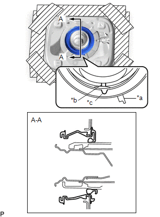
(b) Install the fuel inlet box ring to the fuel tank filler pipe shield as shown in the illustration.
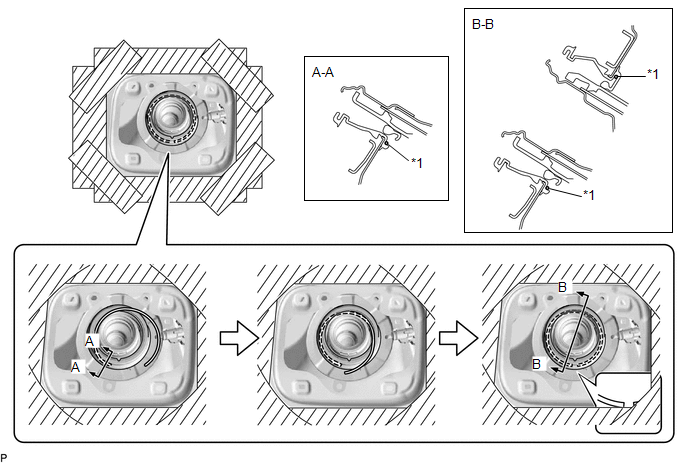
| *1 | Fuel Inlet Box Ring | - | - |
HINT:
Face the end gap of the fuel inlet box ring downward.
(c) Temporarily install the fuel filler opening lid sub-assembly as shown in the illustration.
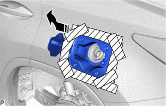
.png) | Install in this Direction |
(d) Install the fuel filler opening lid sub-assembly with the 4 screws.
(e) Install the fuel tank filler pipe shield as shown in the illustration.
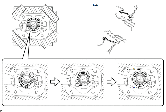
(f) Install the fuel inlet box ring to the fuel tank filler pipe shield as shown in the illustration.
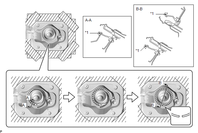
| *1 | Fuel Inlet Box Ring | - | - |
HINT:
Face the end gap of the fuel inlet box ring downward.
2. INSTALL FUEL TANK CAP ASSEMBLY
(a) Engage the clamp.
(b) Install the fuel tank cap assembly as shown in the illustration.
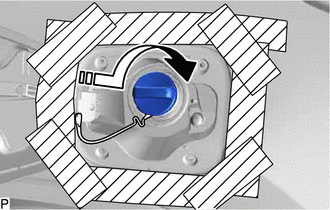
| | Install in this Direction |
3. INSTALL FUEL FILLER OPENING LID ASSEMBLY
(a) Engage the 4 guides and claw to install the fuel filler opening lid assembly as shown in the illustration.
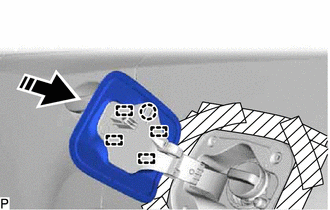
| | Install in this Direction |
(b) Remove the protective tape.
4. INSTALL REAR WHEEL HOUSE LINER LH
(a) Install the rear wheel house liner LH with the 9 nuts.
(b) Install the clip.
(c) Install 2 new grommets.
(d) Install the 2 screws.
(e) Install the screw.
5. INSTALL REAR WHEEL LH
Click here .gif)
6. INSTALL FUEL LID LOCK WITH MOTOR ASSEMBLY
Click here
 Removal
REMOVAL PROCEDURE 1. PRECAUTION Click here 2. REMOVE FUEL LID LOCK WITH MOTOR ASSEMBLY Click here 3. REMOVE REAR WHEEL LH Click here 4. REMOVE REAR WHEEL HOUSE LINER LH (a) Remove the scr ...
 Hood
Hood
...
Other materials:
Lexus RX (RX 350L, RX450h) 2016-2026 Repair Manual > Meter / Gauge System: Tachometer Malfunction
DESCRIPTION In this circuit, the combination meter assembly receives engine speed signals from the ECM via CAN communication. The combination meter assembly displays the engine speed calculated based on the data received from the ECM. WIRING DIAGRAM CAUTION / NOTICE / HINT NOTICE:
When replacing ...
Lexus RX (RX 350L, RX450h) 2016-2026 Owners Manual > Driving procedures: EV drive mode
In EV drive mode, electric power is supplied by the hybrid battery
(traction
battery), and only the electric motor (traction motor) is used to drive the
vehicle.
This mode allows you to drive in residential areas early in the morning and late
at night, or in indoor parking lots, etc., witho ...
Lexus RX (RX 350L, RX450h) 2016-{YEAR} Owners Manual
- For your information
- Pictorial index
- For safety and security
- Instrument cluster
- Operation of each component
- Driving
- Lexus Display Audio system
- Interior features
- Maintenance and care
- When trouble arises
- Vehicle specifications
- For owners
Lexus RX (RX 350L, RX450h) 2016-{YEAR} Repair Manual

0.0107