Lexus RX (RX 350L, RX450h) 2016-2026 Repair Manual: Removal
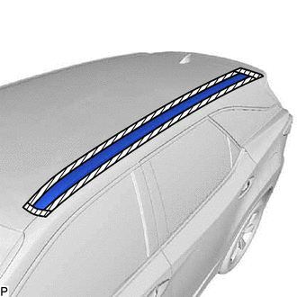
REMOVAL
CAUTION / NOTICE / HINT
The necessary procedures (adjustment, calibration, initialization or registration) that must be performed after parts are removed and installed, or replaced during roof rack removal/installation are shown below.
Necessary Procedures After Parts Removed/Installed/Replaced| Replaced Part or Performed Procedure | Necessary Procedure | Effect/Inoperative Function when Necessary Procedure not Performed | Link |
|---|---|---|---|
|
*1: When performing learning using the Techstream.
Click here | |||
| Disconnect cable from negative (-) battery terminal | Memorize steering angle neutral point | Lane Control System | |
| Pre-collision System | |||
| Intelligent Clearance Sonar System*1 | |||
| Parking Assist Monitor System | | ||
| Panoramic View Monitor System | | ||
| Lighting System (w/ Automatic Headlight Beam Level Control System) | | ||
| Initialize back door lock | Power Door Lock Control System | | |
| Reset back door close position | Power Back Door System (w/ Outside Door Control Switch) | | |
CAUTION:
Some of these service operations affect the SRS airbag system. Read the precautionary notices concerning the SRS airbag system before servicing.
.png)
Click here .gif)
HINT:
- Use the same procedure for the RH side and LH side.
- The following procedure is for the LH side.
PROCEDURE
1. REMOVE CURTAIN SHIELD AIRBAG ASSEMBLY
Click here
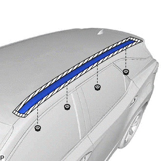
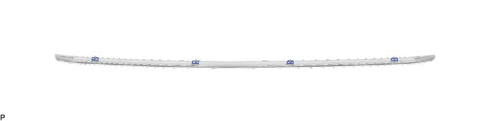
2. REMOVE ROOF RACK ASSEMBLY LH
(a) Apply protective tape around the roof rack assembly LH.
.png) | Protective Tape |
| (b) Remove the 4 nuts. |
|
(c) Disengage the claw as shown in the illustration to remove the roof rack assembly LH.
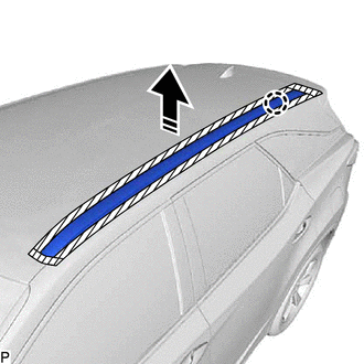
.png) | Remove in this Direction |
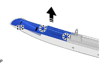
3. REMOVE REAR ROOF RACK LEG CUSHION LH
(a) Disengage the 2 claws and guide as shown in the illustration to remove the rear roof rack leg cushion LH.
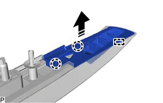
| | Remove in this Direction |
4. REMOVE FRONT ROOF RACK RETAINER LH
(a) Disengage the claw as shown in the illustration to remove the front roof rack retainer LH.
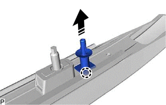
| | Remove in this Direction |
5. REMOVE FRONT ROOF RACK LEG CUSHION LH
(a) Disengage the 2 claws and guide as shown in the illustration to remove the front roof rack leg cushion LH.
| | Remove in this Direction |
6. REMOVE NO. 2 ROOF CARRIER PROTECTOR
(a) Remove the No. 2 roof carrier protector as shown in the illustration.
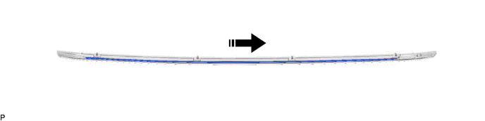
| | Remove in this Direction | - | - |
7. REMOVE NO. 1 ROOF CARRIER PROTECTOR
HINT:
When removing the No. 1 roof carrier protector, heat the roof rack assembly using a heat light.
Standard:
| Item | Temperature |
|---|---|
| Roof Rack Assembly | 40 to 60°C (104 to 140°F) |
CAUTION:
- Do not touch the heat light and heated parts, touching the heat light may result in burns.
- Touching heated parts for a long time may result in burns.
.png)
| *a | Heated Part |
| *b | Heat Light |
NOTICE:
Do not heat the roof rack assembly excessively.
(a) Remove the No. 1 roof carrier protector.
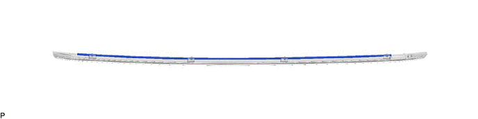
8. REMOVE ROOF CARRIER SEAL
HINT:
When removing the roof carrier seals, heat the roof rack assembly using a heat light.
Standard:
| Item | Temperature |
|---|---|
| Roof Rack Assembly | 40 to 60°C (104 to 140°F) |
CAUTION:
- Do not touch the heat light and heated parts, touching the heat light may result in burns.
- Touching heated parts for a long time may result in burns.
| *a | Heated Part |
| *b | Heat Light |
NOTICE:
Do not heat the roof rack assembly excessively.
(a) Remove the 4 roof carrier seals.
 Installation
INSTALLATION CAUTION / NOTICE / HINT HINT:
Use the same procedure for the RH side and LH side.
The following procedure is for the LH side.
PROCEDURE 1. INSTALL ROOF CARRIER SEAL HINT: When ins ...

Other materials:
Lexus RX (RX 350L, RX450h) 2016-2026 Repair Manual > Luggage Speaker (w/o Rear No. 2 Seat): Removal
REMOVAL CAUTION / NOTICE / HINT The necessary procedures (adjustment, calibration, initialization, or registration) that must be performed after parts are removed and installed, or replaced during rear No. 3 speaker assembly removal/installation are shown below. Necessary Procedures After Parts Remo ...
Lexus RX (RX 350L, RX450h) 2016-2026 Repair Manual > Automatic Transaxle System: Lost Communication with ECM/PCM "A" Missing Message (U010087)
DESCRIPTION The engine control unit and transmission control unit are located inside the ECM. The engine control unit intercommunicates with the transmission control unit using CAN communication. If there is a problem in this intercommunication, the ECM stores this DTC. DTC No. Detection Item ...
Lexus RX (RX 350L, RX450h) 2016-{YEAR} Owners Manual
- For your information
- Pictorial index
- For safety and security
- Instrument cluster
- Operation of each component
- Driving
- Lexus Display Audio system
- Interior features
- Maintenance and care
- When trouble arises
- Vehicle specifications
- For owners
Lexus RX (RX 350L, RX450h) 2016-{YEAR} Repair Manual

0.01