Lexus RX (RX 350L, RX450h) 2016-2026 Repair Manual: Switch Lights of Remote Touch do not Illuminate
DESCRIPTION
Power is supplied to the remote touch (remote operation controller assembly) switch illumination when the light control switch is in the tail or head position.
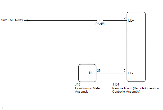
WIRING DIAGRAM
CAUTION / NOTICE / HINT
NOTICE:
Inspect the fuse for circuits related to this system before performing the following procedure.
PROCEDURE
| 1. | CHECK SYMPTOMS |
| (a) Perform the following procedure and check the switch illumination again. (1) If the vehicle is in a bright area, move it to a dark area. HINT: When the vehicle is in a bright area, the switch illumination may not turn on due to the automatic dimmer function. (2) Set the rheostat to maximum brightness. HINT: If the brightness of the rheostat is set to low, switch illumination may not be recognized even when the switch illumination turns on. (3) If the light control switch is in the AUTO position, turn it to the tail or head position. HINT: If the light control switch is in the AUTO position, the switch illumination will not turn on unless the surrounding area is dark. OK: Switch illumination turns on. |
|
| OK |  | END |
|

| 2. | REMOTE TOUCH (REMOTE OPERATION CONTROLLER ASSEMBLY) SELF CHECK (SWITCH ILLUMINATION CHECK) |
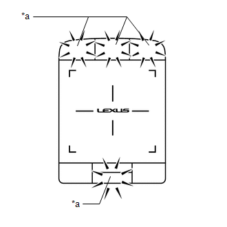
(a) Activate self-diagnostic mode.
Click here .gif)
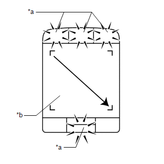
| (b) Check switch illumination. (1) Operate the remote touch screen diagonally from the upper left to the lower right and check that the brightness of the switch illumination changes. NOTICE: Since the remote touch screen may recognize a pinch in/out or flick operation if operated with 2 fingers, always use 1 finger to operate the remote touch screen in self-diagnostic mode. OK: Brightness of the switch illumination changes according to remote touch screen operation. |
|
| NG | | REPLACE REMOTE TOUCH (REMOTE OPERATION CONTROLLER ASSEMBLY) |
|
| 3. | CHECK HARNESS AND CONNECTOR (ILLUMINATION SIGNAL) |
(a) Disconnect the J154 remote touch (remote operation controller assembly) connector.
(b) Measure the voltage according to the value(s) in the table below.
Standard Voltage:
| Tester Connection | Condition | Specified Condition |
|---|---|---|
| J154-2 (ILL+) - Body ground | Light control switch in tail or head position | 11 to 14 V |
| NG | | REPAIR OR REPLACE HARNESS OR CONNECTOR |
|
| 4. | CHECK HARNESS AND CONNECTOR (REMOTE TOUCH (REMOTE OPERATION CONTROLLER ASSEMBLY) - COMBINATION METER ASSEMBLY) |
(a) Disconnect the J154 remote touch (remote operation controller assembly) connector.
(b) Disconnect the J10 combination meter assembly connector.
(c) Measure the resistance according to the value(s) in the table below.
Standard Resistance:
| Tester Connection | Condition | Specified Condition |
|---|---|---|
| J154-5 (ILL-) - J10-39 (ILL-) | Always | Below 1 Ω |
| J154-5 (ILL-) or J10-39 (ILL-) - Body ground | Always | 10 kΩ or higher |
| NG | | REPAIR OR REPLACE HARNESS OR CONNECTOR |
|
| 5. | REPLACE REMOTE TOUCH (REMOTE OPERATION CONTROLLER ASSEMBLY) |
(a) Replace the remote touch (remote operation controller assembly) with a new or known good one.
Click here
(b) Check if the switch illumination turns on.
OK:
The switch illumination turns on when the light control switch is in the tail or head position.
| OK | | END |
| NG | | GO TO METER / GAUGE SYSTEM |
 Remote Touch Screen Does not Generate Vibration Feedback
DESCRIPTION When each button displayed on the multi-display assembly is selected via remote touch screen operation, the remote touch screen generates vibration feedback according to communication betw ...
 Switch Lights of Remote Touch Always Illuminate or cannot be Controlled Using Rheostat
DESCRIPTION Power is supplied to the remote touch (remote operation controller assembly) switch illumination when the light control switch is in the tail or head position. HINT:
When the remote tou ...
Other materials:
Lexus RX (RX 350L, RX450h) 2016-2026 Repair Manual > Sfi System: A/F (O2) Sensor Positive Current Control Bank 1 Sensor 1 Circuit Short to Ground (P223711,...,P225412)
DESCRIPTION Refer to DTC P219519. Click here HINT: Although the DTC titles say O2 sensor, these DTCs relate to the air fuel ratio sensor. DTC No. Detection Item DTC Detection Condition Trouble Area MIL Memory Note P223711 A/F (O2) Sensor Positive Current Control Bank 1 Sensor ...
Lexus RX (RX 350L, RX450h) 2016-2026 Owners Manual > Specifications: Tire information
Typical tire symbols
Full-size tire
Compact spare tire
Tire size
DOT and Tire Identification Number (TIN)
Location of treadwear indicators
Tire ply composition and materials
Plies are layers of rubber-coated parallel cords. Cords are the strands
which form the
plies in a tire. ...
Lexus RX (RX 350L, RX450h) 2016-{YEAR} Owners Manual
- For your information
- Pictorial index
- For safety and security
- Instrument cluster
- Operation of each component
- Driving
- Lexus Display Audio system
- Interior features
- Maintenance and care
- When trouble arises
- Vehicle specifications
- For owners
Lexus RX (RX 350L, RX450h) 2016-{YEAR} Repair Manual

0.0093