Lexus RX (RX 350L, RX450h) 2016-2026 Repair Manual: Terminals Of Ecu
TERMINALS OF ECU
CHECK MAIN BODY ECU (MULTIPLEX NETWORK BODY ECU) AND INSTRUMENT PANEL JUNCTION BLOCK ASSEMBLY
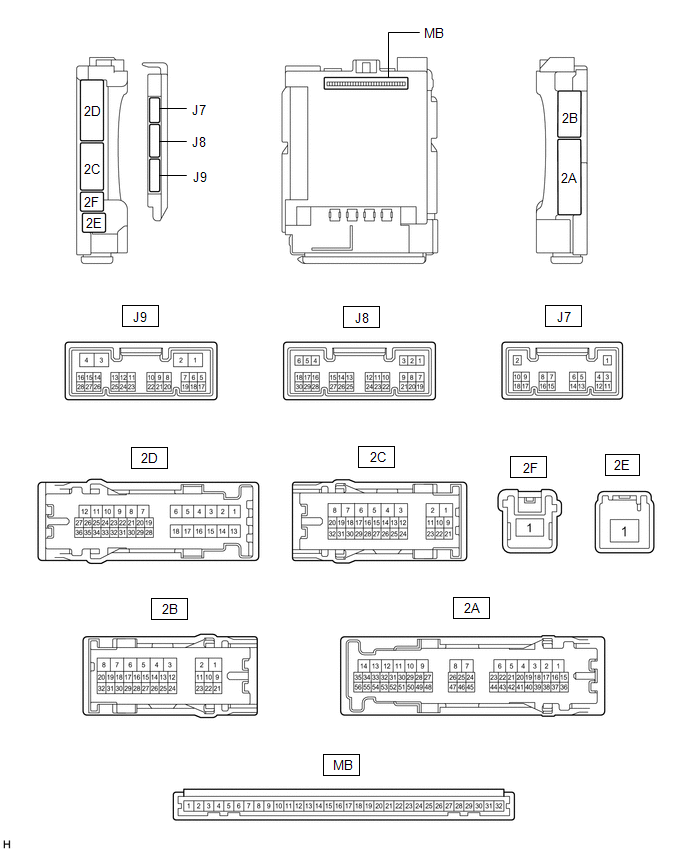
(a) Disconnect the instrument panel junction block assembly and main body ECU (multiplex network body ECU) connectors.
(b) Measure the voltage and resistance according to the value(s) in the table below.
| Terminal No. (Symbol) | Wiring Color | Terminal Description | Condition | Specified Condition |
|---|---|---|---|---|
| 2B-3 - Body ground | W-B - Body ground | Ground | Always | Below 1 Ω |
| 2C-1 - Body ground | GR - Body ground | Battery power supply | Always | 11 to 14 V |
| 2E-1 - Body ground | B - Body ground | Battery power supply | Always | 11 to 14 V |
(c) Connect the instrument panel junction block assembly and main body ECU (multiplex network body ECU) connectors.
(d) Measure the voltage and check for pulses according to the value(s) in the table below.
| Terminal No. (Symbol) | Wiring Color | Terminal Description | Condition | Specified Condition |
|---|---|---|---|---|
| 2C-19 - Body ground | LA-R - Body ground | BKUP LP relay drive output | Engine switch off, reverse (R) not selected | Below 1 V |
| Engine switch on (IG), reverse (R) selected | 11 to 14 V | |||
| 2C-25 - Body ground*1 | B - Body ground | Front fog light drive output | Taillights on, fog light switch in front position | Below 1 V |
| Taillights on, fog light switch in off position | 11 to 14 V | |||
| 2C-31 - Body ground | V - Body ground | H-LP LH relay drive output | Engine switch on (IG) or taillights on | Below 1 V |
| Engine switch off and taillights off | 11 to 14 V | |||
| 2C-32 - Body ground | SB - Body ground | Taillight drive output | Taillights on | 11 to 14 V |
| Taillights off | Below 1 V | |||
| 2D-10 - Body ground | R - Body ground | Back-up lights drive output | Engine switch off, reverse (R) not selected | Below 1 V |
| Engine switch on (IG), reverse (R) selected | 11 to 14 V | |||
| 2D-30 - Body ground | B - Body ground | Taillights, rear side marker lights and license plate lights drive output | Taillights on | 11 to 14 V |
| Taillights off | Below 1 V | |||
| J8-1 (DIM) - Body ground | L - Body ground | H-LP RH relay drive output | Engine switch on (IG) or taillights on | Below 1 V |
| Engine switch off and taillights off | 11 to 14 V | |||
| J8-8 (A) - Body ground | G - Body ground | Light control switch AUTO position signal input | Light control switch in AUTO position | Below 1 V |
| Light control switch not in AUTO position | Pulse generation | |||
| J8-10 (HF) - Body ground | W - Body ground | Dimmer switch high flash position signal input | Dimmer switch in high flash position | Below 1 V |
| Dimmer switch not in high flash position | Pulse generation | |||
| J8-12 (HEAD) - Body ground | Y - Body ground | Light control switch head position input | Light control switch in head position | Below 1 V |
| Light control switch not in head position | Pulse generation | |||
| J8-19 (CLTB) - J8-21 (CLTE) | V - Y | Automatic light control sensor power supply output | Engine switch off | Below 1 V |
| Engine switch on (IG) | 11 to 14 V | |||
| J8-20 (CLTS) - Body ground | BE - Body ground | Automatic light control sensor signal input | Engine switch off | Below 1 V |
| Engine switch on (IG) | (See waveform 1) Pulse generation | |||
| J8-22 (TAIL) - Body ground | V - Body ground | Light control switch tail position signal input | Taillights on | Below 1 V |
| Taillights off | Pulse generation | |||
| J8-24 (HU) - Body ground | GR - Body ground | Dimmer switch high position signal input | Dimmer switch in high position | Below 1 V |
| Dimmer switch not in high position | Pulse generation | |||
| J8-26 (FFOG) - Body ground*1 | SB - Body ground | Fog light switch front position input | Fog light switch in front position | Below 1 V |
| Fog light switch off | Pulse generation | |||
| J9-4 (MILE) - Body ground | SB - Body ground | Outside handle foot lights drive output | Outside handle foot light illuminates | 11 to 14 V |
| Outside handle foot light off | Below 3 V | |||
| J9-23 (AHBI) - Body ground*2 | G - Body ground | Automatic high beam switch signal input | Automatic high beam switch on | Below 1 V |
| Automatic high beam switch off | Pulse generation |
- *1: w/ Front Fog Light
- *2: w/ Automatic High Beam System
(1) Waveform 1
.png)
| Item | Content |
|---|---|
| Tester Connection | J8-20 (CLTS) - Body ground |
| Tool setting | 2 V/DIV., 10 ms./DIV. |
| Condition | Engine switch on (IG) |
HINT:
The communication waveform changes according to the surrounding brightness.
CHECK NO. 1 HEADLIGHT ECU SUB-ASSEMBLY LH (for Multiple Beam Headlight)
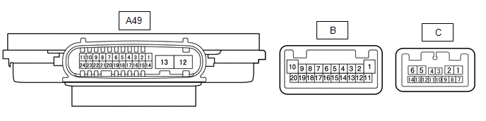
(a) Disconnect the A49 No. 1 headlight ECU sub-assembly LH connector.
(b) Measure the voltage and resistance on the wire harness side connector according to the value(s) in the table below.
| Terminal No. (Symbol) | Wiring Color | Terminal Description | Condition | Specified Condition |
|---|---|---|---|---|
| A49-4 (IG) - Body ground | R - Body ground | Ignition power supply | Engine switch off | Below 1 V |
| Engine switch on (IG) | 11 to 14 V | |||
| A49-12 (GND) - Body ground | W-B - Body ground | Ground | Always | Below 1 Ω |
| A49-13 (ECUB) - Body ground | G - Body ground | Battery power supply | Engine switch off | Below 1 V |
| Engine switch on (IG) | 11 to 14 V |
(c) Connect the A49 No. 1 headlight ECU sub-assembly LH connector.
HINT:
- Since the A49 No. 1 headlight ECU sub-assembly LH connector is a waterproof type connector, the voltage and pulses cannot be checked directly. The values listed are for reference only.
- Since the B and C No. 1 headlight ECU sub-assembly LH connector is connected inside the headlight assembly, the voltage and pulses cannot be checked directly. The values listed are for reference only.
(d) Measure the voltage and check of pulses according to the value(s) in the table below.
| Terminal No. (Symbol) | Wiring Color | Terminal Description | Condition | Specified Condition |
|---|---|---|---|---|
| A49-9 (CRSL) - Body ground*3 | Y - Body ground | Cornering lights drive output | Cornering lights off | Below 1 V |
| Cornering lights on | Pulse generation | |||
| A49-11 (TNS) - Body ground | G - Body ground | Front turn signal light signal input | Engine switch on (IG), front turn signal light off | Below 1 V |
| Engine switch on (IG), front turn signal light blinking | 11 to 14 V ←→ Below 1 V | |||
| A49-16 (SBR) - A49-15 (SGR) | W - R | Rear height control sensor sub-assembly RH power supply | Engine switch on (IG) | 4.75 to 5.25 V |
| A49-17 (SHRL) - A49-15 (SGR) | SB - R | Rear height control sensor sub-assembly RH signal input | Engine switch on (IG), vehicle unloaded, vehicle stopped | Approximately 2.5 V (value decreases as the front of the vehicle is raised) |
| A49-19 (LINS) - Body ground*1 | L - Body ground | LIN communication line | Engine switch off | Below 1 V |
| Engine switch on (IG) | Pulse generation | |||
| A49-20 (LINL) - Body ground | P - Body ground | LIN communication line | Engine switch off | Below 1 V |
| Engine switch on (IG) | Pulse generation | |||
| A49-21 (LCL) - Body ground | W - Body ground | CAN communication line | Engine switch off | Below 1 V |
| Engine switch on (IG) | Pulse generation | |||
| A49-22 (LCH) - Body ground | G - Body ground | CAN communication line | Engine switch off | Below 1 V |
| Engine switch on (IG) | Pulse generation | |||
| A49-23 (CANL) - Body ground | LG - Body ground | CAN communication line | Engine switch off | Below 1 V |
| Engine switch on (IG) | Pulse generation | |||
| A49-24 (CANH) - Body ground | B - Body ground | CAN communication line | Engine switch off | Below 1 V |
| Engine switch on (IG) | Pulse generation | |||
| B-2 (LOLED2) - B-3 (LOLED1) | - | Low beam headlights/high beam headlights drive output | Low beam headlights off | Below 1 V |
| Low beam headlights on | 24.2 to 35.4 V | |||
| B-4 (FANB) - B-14 (FANG) | - | Headlight fan power source | Low beam headlights off | Below 1 V |
| Low beam headlights on | 4.5 to 5.5 V | |||
| B-9 (ACTBI) - B-17 (ACTGI) | - | Headlight swivel motor and headlight leveling motor power source | Engine switch off | Below 1 V |
| Engine switch on (IG) | 11 to 14 V | |||
| B-10 (DRL/CLL+) - B-1 (DRL/CLL-) | - | Parking lights/daytime running lights power source | Parking lights and daytime running lights off | Below 1 V |
| Parking lights and daytime running lights on | 11 to 14 V | |||
| B-15 (FANP) - B-14 (FANG) | - | Headlight fan control signal input | Low beam headlights off | Below 1 V |
| Low beam headlights on | Pulse generation | |||
| B-16 (PWM1) - B-1 (DRL/CLL-) | - | Parking lights/daytime running lights control signal output | Parking lights and daytime running lights off | Below 1 V |
| Parking lights and daytime running lights on | Pulse generation | |||
| B-18 (FSML+) - B-12 (FSML-)*2 | - | Front side marker lights drive output | Front side marker lights off | Below 1 V |
| Front side marker lights on | 11 to 14 V | |||
| B-19 (HI_SOL+) - B-11 (HI_SOL-) | - | High beam headlights drive output | High beam headlights off | Below 1 V |
| High beam headlights on | 11 to 14 V | |||
| B-20 (TURN+) - B-13 (TURN-) | - | Front turn signal light signal output | Engine switch on (IG), front turn signal light off | Below 1 V |
| Engine switch on (IG), front turn signal light blinking | 11 to 14 V ←→ Below 1 V | |||
| C-4 (LINSI) - Body ground | - | LIN communication line | Engine switch off | Below 1 V |
| Engine switch on (IG) | Pulse generation | |||
| C-13 (LINLI) - Body ground | - | LIN communication line | Engine switch off | Below 1 V |
| Engine switch on (IG) | Pulse generation |
- *1: w/ AFS
- *2: w/ Front Side Marker Light
- *3: w/ Front Fog Light
CHECK NO. 1 HEADLIGHT ECU SUB-ASSEMBLY LH (for Single Beam Headlight)
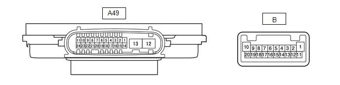
(a) Disconnect the A49 No. 1 headlight ECU sub-assembly LH connector.
(b) Measure the voltage and resistance on the wire harness side connector according to the value(s) in the table below.
| Terminal No. (Symbol) | Wiring Color | Terminal Description | Condition | Specified Condition |
|---|---|---|---|---|
| A49-4 (IG) - Body ground | R - Body ground | Ignition power supply | Engine switch off | Below 1 V |
| Engine switch on (IG) | 11 to 14 V | |||
| A49-12 (GND) - Body ground | W-B - Body ground | Ground | Always | Below 1 Ω |
| A49-13 (ECUB) - Body ground | G - Body ground | Battery power supply | Engine switch off | Below 1 V |
| Engine switch on (IG) | 11 to 14 V |
(c) Connect the A49 No. 1 headlight ECU sub-assembly LH connector.
HINT:
- Since the A49 No. 1 headlight ECU sub-assembly LH connector is a waterproof type connector, the voltage and pulses cannot be checked directly. The values listed are for reference only.
- Since the B No. 1 headlight ECU sub-assembly LH connector is connected inside the headlight assembly, the voltage and pulses cannot be checked directly. The values listed are for reference only.
(d) Measure the voltage and check of pulses according to the value(s) in the table below.
| Terminal No. (Symbol) | Wiring Color | Terminal Description | Condition | Specified Condition |
|---|---|---|---|---|
| A49-9 (CRSL) - Body ground*2 | Y - Body ground | Cornering lights drive output | Cornering lights off | Below 1 V |
| Cornering lights on | Pulse generation | |||
| A49-11 (TNS) - Body ground | G - Body ground | Front turn signal light signal input | Engine switch on (IG), front turn signal light off | Below 1 V |
| Engine switch on (IG), front turn signal light blinking | 11 to 14 V ←→ Below 1 V | |||
| A49-16 (SBR) - A49-15 (SGR) | W - R | Rear height control sensor sub-assembly RH power supply | Engine switch on (IG) | 4.75 to 5.25 V |
| A49-17 (SHRL) - A49-15 (SGR) | SB - G | Rear height control sensor sub-assembly RH signal input | Engine switch on (IG), vehicle unloaded, vehicle stopped | Approximately 2.5 V (value decreases as the front of the vehicle is raised) |
| A49-20 (LINL) - Body ground | P - Body ground | LIN communication line | Engine switch off | Below 1 V |
| Engine switch on (IG) | Pulse generation | |||
| A49-23 (CANL) - Body ground | LG - Body ground | CAN communication line | Engine switch off | Below 1 V |
| Engine switch on (IG) | Pulse generation | |||
| A49-24 (CANH) - Body ground | B - Body ground | CAN communication line | Engine switch off | Below 1 V |
| Engine switch on (IG) | Pulse generation | |||
| B-4 (LOLED2) - B-5 (LOLED1) | - | Low beam headlights/high beam headlights drive output | Low beam headlights off | Below 1 V |
| Low beam headlights on | 11.1 to 17.7 V | |||
| B-7 (ACTBI) - B-17 (ACTGI) | - | Headlight leveling motor power source | Engine switch off | Below 1 V |
| Engine switch on (IG) | 11 to 14 V | |||
| B-8 (ACTSI) - B-17 (ACTGI) | - | Headlight leveling motor signal output | Engine switch on (IG), low beam headlights on, vehicle height not changed | Below 1 V |
| Engine switch on (IG), low beam headlights on, vehicle height changed and maintained for more than 3 seconds | 1.0 to 14 V | |||
| B-9 (TURN+) - B-13 (TURN-) | - | Front turn signal light signal output | Engine switch on (IG), front turn signal light off | Below 1 V |
| Engine switch on (IG), front turn signal light blinking | 11 to 14 V ←→ Below 1 V | |||
| B-10 (HI+) - B-1 (HI-) | - | Parking lights/daytime running lights power source | Parking lights and daytime running lights off | Below 1 V |
| Parking lights and daytime running lights on | 11 to 14 V | |||
| B-16 (PWM1) - B-1 (HI-) | - | Parking lights/daytime running lights control signal output | Parking lights and daytime running lights off | Below 1 V |
| Parking lights and daytime running lights on | Pulse generation | |||
| B-18 (FSML+) - B-12 (FSML-)*1 | - | Front side marker lights drive output | Front side marker lights off | Below 1 V |
| Front side marker lights on | 11 to 14 V | |||
| B-20 (DRL+) - B-11 (DRL-) | - | High beam headlights drive output | High beam headlights off | Below 1 V |
| High beam headlights on | 11 to 14 V |
- *1: w/ Front Side Marker Light
- *2: w/ Front Fog Light
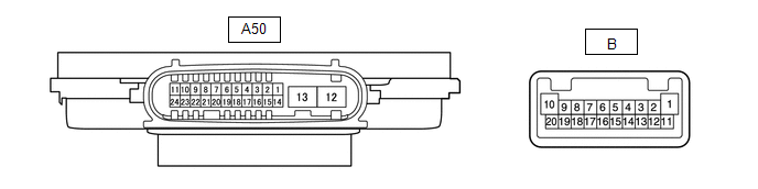
CHECK NO. 1 HEADLIGHT ECU SUB-ASSEMBLY RH (for Multiple Beam Headlight)

(a) Disconnect the A50 No. 1 headlight ECU sub-assembly RH connector.
(b) Measure the voltage and resistance on the wire harness side connector according to the value(s) in the table below.
| Terminal No. (Symbol) | Wiring Color | Terminal Description | Condition | Specified Condition |
|---|---|---|---|---|
| A50-4 (IG) - Body ground | L - Body ground | Ignition power supply | Engine switch off | Below 1 V |
| Engine switch on (IG) | 11 to 14 V | |||
| A50-12 (GND) - Body ground | W-B - Body ground | Ground | Always | Below 1 Ω |
| A50-13 (ECUB) - Body ground | R - Body ground | Battery power supply | Engine switch off | Below 1 V |
| Engine switch on (IG) | 11 to 14 V |
(c) Connect the A50 No. 1 headlight ECU sub-assembly RH connector.
HINT:
- Since the A50 No. 1 headlight ECU sub-assembly RH connector is a waterproof type connector, the voltage and pulses cannot be checked directly. The values listed are for reference only.
- Since the B and C No. 1 headlight ECU sub-assembly RH connector is connected inside the headlight assembly, the voltage and pulses cannot be checked directly. The values listed are for reference only.
(d) Measure the voltage and check of pulses according to the value(s) in the table below.
| Terminal No. (Symbol) | Wiring Color | Terminal Description | Condition | Specified Condition |
|---|---|---|---|---|
| A50-7 (HLC) - Body ground*1 | B - Body ground | Headlight cleaner motor operation signal | Engine switch on (IG), light control switch head and headlight cleaner motor operating | Below 1 V |
| Engine switch on (IG), light control switch head and headlight cleaner motor not operating | 11 to 14 V | |||
| A50-9 (CRSR) - Body ground*4 | LG - Body ground | Cornering lights drive output | Cornering lights off | Below 1 V |
| Cornering lights on | Pulse generation | |||
| A50-11 (TNS) - Body ground | V - Body ground | Front turn signal light signal input | Engine switch on (IG), front turn signal light off | Below 1 V |
| Engine switch on (IG), front turn signal light blinking | 11 to 14 V ←→ Below 1 V | |||
| A50-18 (FRWA) - Body ground*1 | Y - Body ground | Washer switch operation signal | Engine switch on (IG), washer switch on | Below 1 V |
| Engine switch on (IG), washer switch off | 11 to 14 V | |||
| A50-19 (LINS) - Body ground*2 | L - Body ground | LIN communication line | Engine switch off | Below 1 V |
| Engine switch on (IG) | Pulse generation | |||
| A50-20 (LINL) - Body ground | P - Body ground | LIN communication line | Engine switch off | Below 1 V |
| Engine switch on (IG) | Pulse generation | |||
| A50-21 (LCL) - Body ground | W - Body ground | CAN communication line | Engine switch off | Below 1 V |
| Engine switch on (IG) | Pulse generation | |||
| A50-22 (LCH) - Body ground | G - Body ground | CAN communication line | Engine switch off | Below 1 V |
| Engine switch on (IG) | Pulse generation | |||
| B-2 (LOLED2) - B-3 (LOLED1) | - | Low beam headlights/high beam headlights drive output | Low beam headlights off | Below 1 V |
| Low beam headlights on | 24.2 to 35.4 V | |||
| B-4 (FANB) - B-14 (FANG) | - | Headlight fan power source | Low beam headlights off | Below 1 V |
| Low beam headlights on | 4.5 to 5.5 V | |||
| B-9 (ACTBI) - B-17 (ACTGI) | - | Headlight swivel motor and headlight leveling motor power source | Engine switch off | Below 1 V |
| Engine switch on (IG) | 11 to 14 V | |||
| B-10 (DRL/CLL+) - B-1 (DRL/CLL-) | - | Parking lights/daytime running lights power source | Parking lights and daytime running lights off | Below 1 V |
| Parking lights and daytime running lights on | 11 to 14 V | |||
| B-15 (FANP) - B-14 (FANG) | - | Headlight fan control signal input | Low beam headlights off | Below 1 V |
| Low beam headlights on | Pulse generation | |||
| B-16 (PWM1) - B-1 (DRL/CLL-) | - | Parking lights/daytime running lights control signal output | Parking lights and daytime running lights off | Below 1 V |
| Parking lights and daytime running lights on | Pulse generation | |||
| B-18 (FSML+) - B-12 (FSML-)*3 | - | Front side marker lights drive output | Front side marker lights off | Below 1 V |
| Front side marker lights on | 11 to 14 V | |||
| B-19 (HI_SOL+) - B-11 (HI_SOL-) | - | High beam headlights drive output | High beam headlights off | Below 1 V |
| High beam headlights on | 11 to 14 V | |||
| B-20 (TURN+) - B-13 (TURN-) | - | Front turn signal light signal output | Engine switch on (IG), front turn signal light off | Below 1 V |
| Engine switch on (IG), front turn signal light blinking | 11 to 14 V ←→ Below 1 V | |||
| C-4 (LINSI) - Body ground | - | LIN communication line | Engine switch off | Below 1 V |
| Engine switch on (IG) | Pulse generation | |||
| C-13 (LINLI) - Body ground | - | LIN communication line | Engine switch off | Below 1 V |
| Engine switch on (IG) | Pulse generation |
- *1: w/ Headlight Cleaner System
- *2: w/ AFS
- *3: w/ Front Side Marker Light
- *4: w/ Front Fog Light
CHECK NO. 1 HEADLIGHT ECU SUB-ASSEMBLY RH (for Single Beam Headlight)
(a) Disconnect the A50 No. 1 headlight ECU sub-assembly RH connector.
(b) Measure the voltage and resistance on the wire harness side connector according to the value(s) in the table below.
| Terminal No. (Symbol) | Wiring Color | Terminal Description | Condition | Specified Condition |
|---|---|---|---|---|
| A50-4 (IG) - Body ground | L - Body ground | Ignition power supply | Engine switch off | Below 1 V |
| Engine switch on (IG) | 11 to 14 V | |||
| A50-12 (GND) - Body ground | W-B - Body ground | Ground | Always | Below 1 Ω |
| A50-13 (ECUB) - Body ground | R - Body ground | Battery power supply | Engine switch off | Below 1 V |
| Engine switch on (IG) | 11 to 14 V |
(c) Connect the A50 No. 1 headlight ECU sub-assembly RH connector.
HINT:
- Since the A50 No. 1 headlight ECU sub-assembly RH connector is a waterproof type connector, the voltage and pulses cannot be checked directly. The values listed are for reference only.
- Since the B No. 1 headlight ECU sub-assembly RH connector is connected inside the headlight assembly, the voltage and pulses cannot be checked directly. The values listed are for reference only.
(d) Measure the voltage and check of pulses according to the value(s) in the table below.
| Terminal No. (Symbol) | Wiring Color | Terminal Description | Condition | Specified Condition |
|---|---|---|---|---|
| A50-7 (HLC) - Body ground*1 | B - Body ground | Headlight cleaner motor operation signal | Engine switch on (IG), light control switch head and headlight cleaner motor operating | Below 1 V |
| Engine switch on (IG), light control switch head and headlight cleaner motor not operating | 11 to 14 V | |||
| A50-9 (CRSR) - Body ground*3 | LG - Body ground | Cornering lights drive output | Cornering lights off | Below 1 V |
| Cornering lights on | Pulse generation | |||
| A50-11 (TNS) - Body ground | V - Body ground | Front turn signal light signal input | Engine switch on (IG), front turn signal light off | Below 1 V |
| Engine switch on (IG), front turn signal light blinking | 11 to 14 V ←→ Below 1 V | |||
| A50-18 (FRWA) - Body ground*1 | Y - Body ground | Washer switch operation signal | Engine switch on (IG), washer switch on | Below 1 V |
| Engine switch on (IG), washer switch off | 11 to 14 V | |||
| A50-20 (LINL) - Body ground | P - Body ground | LIN communication line | Engine switch off | Below 1 V |
| Engine switch on (IG) | Pulse generation | |||
| B-4 (LOLED2) - B-5 (LOLED1) | - | Low beam headlights/high beam headlights drive output | Low beam headlights off | Below 1 V |
| Low beam headlights on | 11.1 to 17.7 V | |||
| B-7 (ACTBI) - B-17 (ACTGI) | - | Headlight leveling motor power source | Engine switch off | Below 1 V |
| Engine switch on (IG) | 11 to 14 V | |||
| B-8 (ACTSI) - B-17 (ACTGI) | - | Headlight leveling motor signal output | Engine switch on (IG), low beam headlights on, vehicle height not changed | Below 1 V |
| Engine switch on (IG), low beam headlights on, vehicle height changed and maintained for more than 3 seconds | 1.0 to 14 V | |||
| B-9 (TURN+) - B-13 (TURN-) | - | Front turn signal light signal output | Engine switch on (IG), front turn signal light off | Below 1 V |
| Engine switch on (IG), front turn signal light blinking | 11 to 14 V ←→ Below 1 V | |||
| B-10 (HI+) - B-1 (HI-) | - | Parking lights/daytime running lights power source | Parking lights and daytime running lights off | Below 1 V |
| Parking lights and daytime running lights on | 11 to 14 V | |||
| B-16 (PWM1) - B-1 (HI-) | - | Parking lights/daytime running lights control signal output | Parking lights and daytime running lights off | Below 1 V |
| Parking lights and daytime running lights on | Pulse generation | |||
| B-18 (FSML+) - B-12 (FSML-)*2 | - | Front side marker lights drive output | Front side marker lights off | Below 1 V |
| Front side marker lights on | 11 to 14 V | |||
| B-20 (DRL+) - B-11 (DRL-) | - | High beam headlights drive output | High beam headlights off | Below 1 V |
| High beam headlights on | 11 to 14 V |
- *1: w/ Headlight Cleaner System
- *2: w/ Front Side Marker Light
- *3: w/ Front Fog Light
CHECK COMBINATION METER ASSEMBLY
Click here .gif)
CHECK FORWARD RECOGNITION CAMERA (w/ Automatic High Beam System)
Click here
 Problem Symptoms Table
PROBLEM SYMPTOMS TABLE NOTICE:
Before replacing the main body ECU (multiplex network body ECU), refer to Registration.
Click here
If the No. 1 headlight ECU sub-assembly LH has been replaced, ...
 Dtc Check / Clear
DTC CHECK / CLEAR CHECK FOR DTC (MAIN BODY) (a) Connect the Techstream to the DLC3. (b) Turn the engine switch on (IG). (c) Turn the Techstream on. (d) Enter the following menus: Body Electrical / Mai ...
Other materials:
Lexus RX (RX 350L, RX450h) 2016-2026 Repair Manual > Wireless Door Lock Control System: Customize Parameters
CUSTOMIZE PARAMETERS CUSTOMIZE WIRELESS DOOR LOCK CONTROL SYSTEM HINT: The following items can be customized. NOTICE:
When the customer requests a change in a function, first make sure that the function can be customized.
Be sure to make a note of the current settings before customizing.
When ...
Lexus RX (RX 350L, RX450h) 2016-2026 Repair Manual > Power Mirror Control System (w/ Memory): Driver Side Power Mirror cannot be Adjusted with Power Mirror Switch
DESCRIPTION The multiplex network master switch assembly sends the mirror adjust switch signals to the main body ECU (multiplex network body ECU) via LIN communication. The main body ECU (multiplex network body ECU) then sends the received mirror adjust switch signals to the outer mirror control ECU ...
Lexus RX (RX 350L, RX450h) 2016-{YEAR} Owners Manual
- For your information
- Pictorial index
- For safety and security
- Instrument cluster
- Operation of each component
- Driving
- Lexus Display Audio system
- Interior features
- Maintenance and care
- When trouble arises
- Vehicle specifications
- For owners
Lexus RX (RX 350L, RX450h) 2016-{YEAR} Repair Manual

0.0102