Lexus RX (RX 350L, RX450h) 2016-2026 Repair Manual: Steering Pad Switch Circuit
DESCRIPTION
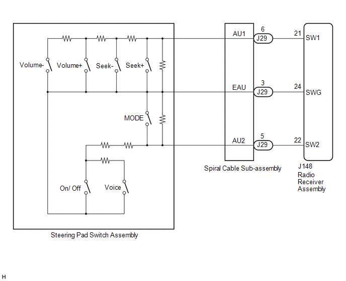
This circuit sends an operation signal from the steering pad switch assembly to the radio receiver assembly.
If there is an open in the circuit, the audio and visual system cannot be operated using the steering pad switch assembly.
If there is a short in the circuit, the same condition as when a switch is continuously depressed occurs.
Therefore, the radio receiver assembly cannot be operated using the steering pad switch assembly, also the radio receiver assembly itself will not function.
WIRING DIAGRAM
CAUTION / NOTICE / HINT
NOTICE:
The vehicle is equipped with a Supplemental Restraint System (SRS) which includes components such as airbags. Before servicing (including removal or installation of parts), be sure to read the precaution for Supplemental Restraint System.
Click here .gif)
PROCEDURE
| 1. | INSPECT STEERING PAD SWITCH ASSEMBLY |
(a) Remove the steering pad switch assembly.
Click here
(b) Inspect the steering pad switch assembly.
Click here
| NG | .gif) | REPLACE STEERING PAD SWITCH ASSEMBLY |
|
.gif)
| 2. | INSPECT SPIRAL CABLE SUB-ASSEMBLY |
(a) Remove the spiral cable sub-assembly.
Click here
(b) Inspect the spiral cable sub-assembly.
Click here
| NG | | REPLACE SPIRAL CABLE SUB-ASSEMBLY |
|
| 3. | CHECK HARNESS AND CONNECTOR (RADIO RECEIVER ASSEMBLY - SPIRAL CABLE SUB-ASSEMBLY) |
(a) Disconnect the J148 radio receiver assembly connector.
(b) Disconnect the J29 spiral with sensor cable sub-assembly connector.
(c) Measure the resistance according to the value(s) in the table below.
Standard Resistance:
| Tester Connection | Condition | Specified Condition |
|---|---|---|
| J148-21 (SW1) - J29-6 (AU1) | Always | Below 1 Ω |
| J148-22 (SW2) - J29-5 (AU2) | Always | Below 1 Ω |
| J148-24 (SWG) - J29-3 (EAU) | Always | Below 1 Ω |
| J148-21 (SW1) or J29-6 (AU1) - Body ground | Always | 10 kΩ or higher |
| J148-22 (SW2) or J29-5 (AU2) - Body ground | Always | 10 kΩ or higher |
| J148-24 (SWG) or J29-3 (EAU) - Body ground | Always | 10 kΩ or higher |
| OK | | PROCEED TO NEXT SUSPECTED AREA SHOWN IN PROBLEM SYMPTOMS TABLE |
| NG | | REPAIR OR REPLACE HARNESS OR CONNECTOR |
 Pointer not Displayed on Screen or Pointer does not Move
CAUTION / NOTICE / HINT NOTICE: Depending on the parts that are replaced during vehicle inspection or maintenance, performing initialization, registration or calibration may be needed. Refer to Precau ...
 Illumination Circuit
DESCRIPTION Power is supplied to the radio receiver assembly and steering pad switch assembly illumination when the light control switch is in the tail or head position. WIRING DIAGRAM CAUTION / NOTI ...
Other materials:
Lexus RX (RX 350L, RX450h) 2016-2026 Repair Manual > Meter / Gauge System: Odo/Trip Switch Malfunction
DESCRIPTION In this circuit, the combination meter assembly detects ODO/TRIP switch signals via a direct line. WIRING DIAGRAM CAUTION / NOTICE / HINT NOTICE: When replacing the combination meter assembly, always replace it with a new one. If a combination meter assembly which was installed to anoth ...
Lexus RX (RX 350L, RX450h) 2016-2026 Repair Manual > Electric Parking Brake System: Supply Voltage Circuit IG Open (C123A14)
DESCRIPTION DTC No. Detection Item DTC Detection Condition Trouble Area Memory Note C123A14 Supply Voltage Circuit IG Open
Diagnosis Condition:
Engine switch on (IG)
Malfunction Status:
When the ECM is communicating via CAN communication, IG power is not input to the skid c ...
Lexus RX (RX 350L, RX450h) 2016-{YEAR} Owners Manual
- For your information
- Pictorial index
- For safety and security
- Instrument cluster
- Operation of each component
- Driving
- Lexus Display Audio system
- Interior features
- Maintenance and care
- When trouble arises
- Vehicle specifications
- For owners
Lexus RX (RX 350L, RX450h) 2016-{YEAR} Repair Manual

0.0104