Lexus RX (RX 350L, RX450h) 2016-2026 Repair Manual: Vehicle Speed Signal Circuit between Navigation ECU and Combination Meter
DESCRIPTION
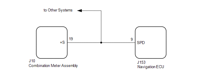
The navigation ECU receives a vehicle speed signal from the combination meter assembly.
HINT:
- A voltage of 12 V or 5 V is output from each ECU and then input to the combination meter assembly. The signal is changed to a pulse signal at the transistor in the combination meter assembly. Each ECU controls its respective systems based on this pulse signal.
- If a short occurs in any of the ECUs or in the wire harness connected to an ECU, all systems in the following diagram will not operate normally.
WIRING DIAGRAM
PROCEDURE
| 1. | CHECK COMBINATION METER ASSEMBLY (OUTPUT WAVEFORM) |
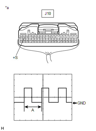
| (a) Check the output waveform. (1) Remove the combination meter assembly with the connector still connected. (2) Connect an oscilloscope to terminal J10-19 (+S) and body ground. (3) Turn the engine switch on (IG). (4) Turn a wheel slowly. (5) Check the signal waveform according to the condition(s) in the table below.
OK: The waveform is similar to that shown in the illustration. HINT: When the system is functioning normally, one wheel revolution generates 4 pulses. As the vehicle speed increases, the width indicated by (A) in the illustration narrows. |
|
| NG |  | GO TO METER / GAUGE SYSTEM |
|

| 2. | CHECK NAVIGATION ECU (INPUT WAVEFORM) |
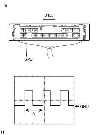
| (a) Check the input waveform. (1) Remove the navigation ECU with the connector(s) still connected. (2) Connect an oscilloscope to terminal J153-9 (SPD) and body ground. (3) Turn the engine switch on (IG). (4) Turn a wheel slowly. (5) Check the signal waveform according to the condition(s) in the table below.
OK: The waveform is similar to that shown in the illustration. HINT: When the system is functioning normally, one wheel revolution generates 4 pulses. As the vehicle speed increases, the width indicated by (A) in the illustration narrows. |
|
| OK | | PROCEED TO NEXT SUSPECTED AREA SHOWN IN PROBLEM SYMPTOMS TABLE |
| NG | | REPAIR OR REPLACE HARNESS OR CONNECTOR |
 AVC-LAN Circuit
DESCRIPTION Each unit of the audio and visual system connected to the AVC-LAN (communication bus) transmits switch signals via AVC-LAN communication. If a short to +B or short to ground occurs in the ...
 Vehicle Speed Signal Circuit between Stereo Component Amplifier and Combination Meter
DESCRIPTION The stereo component amplifier assembly receives a vehicle speed signal from the combination meter assembly to control the ASL function. HINT:
A voltage of 12 V or 5 V is output from ea ...
Other materials:
Lexus RX (RX 350L, RX450h) 2016-2026 Repair Manual > Rear Differential Carrier Assembly: Installation
INSTALLATION CAUTION / NOTICE / HINT CAUTION: The rear differential carrier assembly with differential support is very heavy. Be sure to follow the procedure described in the repair manual, or the engine lifter may suddenly drop. NOTICE: If installing a new rear differential carrier assembly, remove ...
Lexus RX (RX 350L, RX450h) 2016-2026 Repair Manual > Rear Differential Carrier Assembly: Disassembly
DISASSEMBLY CAUTION / NOTICE / HINT NOTICE:
Before installation, thoroughly clean and dry each part and then apply Toyota Genuine Differential gear oil LT SAE 75W-85 GL-5 or equivalent to them.
Do not use alkaline cleaner for aluminum or rubber parts and rear differential case bolts.
Do not c ...
Lexus RX (RX 350L, RX450h) 2016-{YEAR} Owners Manual
- For your information
- Pictorial index
- For safety and security
- Instrument cluster
- Operation of each component
- Driving
- Lexus Display Audio system
- Interior features
- Maintenance and care
- When trouble arises
- Vehicle specifications
- For owners
Lexus RX (RX 350L, RX450h) 2016-{YEAR} Repair Manual

0.0135