Lexus RX (RX 350L, RX450h) 2016-2026 Repair Manual: Diagnosis System
DIAGNOSIS SYSTEM
DESCRIPTION
(a) Blind spot monitor data and Diagnostic Trouble Codes (DTCs) can be read from the Data Link Connector 3 (DLC3) of the vehicle. When the system seems to be malfunctioning, use the Techstream to check for malfunctions and to perform repairs.
CHECK DLC3
(a) Check the DLC3.
Click here .gif)
DIAGNOSIS FUNCTION
(a) The blind spot monitor system displays an error message on the multi-information display to inform the driver that the system is unavailable either temporarily or due to a malfunction.
-
When the system is unavailable temporarily:
Multi-information display displays "BSM not available".
-
When the system is unavailable due to a malfunction:
Multi-information display displays "Check BSM System".
(b) If the RCTA function is not operating correctly, the blind spot monitor system displays the RCTA icon on the multi-display assembly*1 or accessory meter assembly*2 to inform the driver of the malfunction
- *1: for 8 Inch Display
- *2: for 12.3 Inch Display
| Malfunctioning Item | Detection Condition | Malfunction Indication | Suspected Area |
|---|---|---|---|
| System Malfunction Indication |
| ○ | Check for DTCs |
(1) Malfunction Indication
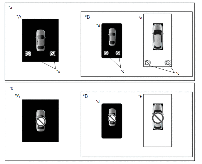
| *A | for 12.3 Inch Display | *B | for 8 Inch Display (w/ Panoramic View Monitor System) |
| *a | System Malfunction Indication | *b | Communication Malfunction Indication |
| *c | RCTA Icon | *d | When panoramic view screen not displayed |
| *e | When panoramic view screen displayed | - | - |
ABNORMALITY HISTORY
HINT:
The abnormality history for a blind spot monitor sensor can be displayed or cleared.
(a) Check abnormality history
(1) Connect the Techstream to the DLC3.
(2) Turn the engine switch on (IG).
(3) Turn the Techstream on.
(4) Turn the blind spot monitor system on.
(5) Enter the following menus: Body Electrical / Blind Spot Monitor Master or Blind Spot Monitor Slave / Utility / BSM Master Abnormal History or BSM Slave Abnormal History.
Body Electrical > Blind Spot Monitor Master > Utility| Tester Display |
|---|
| BSM Master Abnormal History |
| Tester Display |
|---|
| BSM Slave Abnormal History |
(6) Check the results displayed for the abnormality history check.
HINT:
- If "Yes" is displayed, check the suspected area column for each item.
- Abnormality history is stored only for the blind spot monitor sensor for which an abnormality has been detected.
-
If "No" is displayed, refer to Problem Symptoms Table.
Click here
| Tester Display | Item Explanation | Suspected Area |
|---|---|---|
| History of Module Blockage | History of blind spot monitor sensor detection problems due to snow, rain, etc. on the bumper |
|
| History of Low Voltage | History of low supply battery voltage from battery to the blind spot monitor sensor | Power Source Circuit Click here |
| History of High Voltage | History of high supply battery voltage from battery to the blind spot monitor sensor | |
| History of Low Temperature | History of low temperature for the blind spot monitor sensor |
|
| History of High Temperature | History of high temperature for the blind spot monitor sensor |
(b) Clearing abnormality history
(1) Connect the Techstream to the DLC3.
(2) Turn the engine switch on (IG).
(3) Turn the Techstream on.
(4) Turn the blind spot monitor system on.
(5) Enter the following menus: Body Electrical / Blind Spot Monitor Master or Blind Spot Monitor Slave / Utility / BSM Master Abnormal History or BSM Slave Abnormal History.
Body Electrical > Blind Spot Monitor Master > Utility| Tester Display |
|---|
| BSM Master Abnormal History |
| Tester Display |
|---|
| BSM Slave Abnormal History |
(6) Clear the abnormality history.
 Terminals Of Ecu
TERMINALS OF ECU BLIND SPOT MONITOR SENSOR LH (MASTER) Terminal No. (Symbol) Wiring Color Terminal Description Condition Specified Condition X2-4 (OMIL) - X2-10 (BLGD) G - W-B Oute ...
 Dtc Check / Clear
DTC CHECK / CLEAR CHECK DTC (a) Connect the Techstream to the DLC3. (b) Turn the engine switch on (IG). (c) Turn the blind spot monitor system on. (d) Turn the Techstream on. (e) Enter the following m ...
Other materials:
Lexus RX (RX 350L, RX450h) 2016-2026 Repair Manual > Can Communication System: Lost Communication with "Door Control Module B" (U0200)
DESCRIPTION DTC No. Detection Item DTC Detection Condition Trouble Area Note U0200 Lost Communication with "Door Control Module B" No communication from the outer mirror control ECU assembly (for driver side) continues.
Outer mirror control ECU assembly (for driver side) bran ...
Lexus RX (RX 350L, RX450h) 2016-2026 Repair Manual > Rear Center Seat Outer Belt Assembly(w/o Rear No. 2 Seat): Components
COMPONENTS ILLUSTRATION *A for Manual Seat *B for Power Seat *1 NO. 1 RECLINING ADJUSTER RELEASE HANDLE RH *2 POWER SEAT SWITCH ASSEMBLY *3 REAR SEAT COVER CAP RH *4 SEPARATE TYPE REAR SEAT CUSHION COVER WITH PAD ILLUSTRATION *A for TMK Made - - *1 RE ...
Lexus RX (RX 350L, RX450h) 2016-{YEAR} Owners Manual
- For your information
- Pictorial index
- For safety and security
- Instrument cluster
- Operation of each component
- Driving
- Lexus Display Audio system
- Interior features
- Maintenance and care
- When trouble arises
- Vehicle specifications
- For owners
Lexus RX (RX 350L, RX450h) 2016-{YEAR} Repair Manual

0.0122