Lexus RX (RX 350L, RX450h) 2016-2026 Repair Manual: Installation
INSTALLATION
PROCEDURE
1. INSTALL WATER INLET WITH THERMOSTAT SUB-ASSEMBLY
(a) Install a new gasket to the water inlet with thermostat sub-assembly.
(b) Install the water inlet with thermostat sub-assembly with the 2 bolts and 2 nuts.
Torque:
10 N·m {102 kgf·cm, 7 ft·lbf}
2. CONNECT WATER BY-PASS HOSE
(a) Connect the water by-pass hose and slide the clip to secure it.
3. CONNECT NO. 2 RADIATOR HOSE
(a) Connect the No. 2 radiator hose and slide the clip to secure it.
4. INSTALL FRONT NO. 1 ENGINE MOUNTING BRACKET LH
Click here .gif)
5. CONNECT ENGINE WIRE
(a) Connect the water inlet with thermostat sub-assembly connector.
(b) Connect the engine wire with the bolt.
Torque:
8.4 N·m {86 kgf·cm, 74 in·lbf}
6. INSTALL ENGINE MOUNTING SPACER
(a) Install the engine mounting spacer with the 2 bolts.
Torque:
71 N·m {724 kgf·cm, 52 ft·lbf}
7. INSTALL ENGINE MOUNTING INSULATOR SUB-ASSEMBLY RH
(a) Install the engine mounting insulator sub-assembly RH with the 2 bolts and nut.
Torque:
71 N·m {724 kgf·cm, 52 ft·lbf}
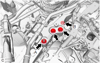
| (b) Install the engine mounting insulator sub-assembly RH to the front No. 1 engine mounting bracket LH with the 2 bolts and 2 nuts. Torque: Bolt and Nut (A) : 71 N·m {724 kgf·cm, 52 ft·lbf} Nut (B) : 40 N·m {408 kgf·cm, 30 ft·lbf} |
|
(c) Install the cooler bracket to the engine mounting insulator sub-assembly RH with the bolt.
Torque:
9.8 N·m {100 kgf·cm, 87 in·lbf}
8. INSTALL NO. 2 ENGINE MOUNTING STAY RH
Click here
9. REMOVE ENGINE SUPPORT BRIDGE
for 2WD: Click here
for AWD: Click here
10. CONNECT NO. 1 RADIATOR HOSE
Click here
11. INSTALL BRAKE ACTUATOR ASSEMBLY
Click here
12. INSTALL WIRE HARNESS CLAMP BRACKET
for 2WD: Click here
for AWD: Click here
13. INSTALL FUEL PUMP PROTECTOR
Click here
14. INSTALL BATTERY BRACKET REINFORCEMENT
for 2WD: Click here
for AWD: Click here
15. INSTALL BATTERY CARRIER SUB-ASSEMBLY
for 2WD: Click here
for AWD: Click here
16. INSTALL BATTERY
for 2WD: Click here
for AWD: Click here
17. INSTALL INLET AIR CLEANER ASSEMBLY
Click here
18. INSTALL INTAKE AIR SURGE TANK ASSEMBLY
Click here
19. INSTALL ECM
Click here
20. INSTALL NO. 2 ENGINE UNDER COVER
Click here
21. INSTALL OUTER COWL TOP PANEL SUB-ASSEMBLY
Click here
22. INSTALL WINDSHIELD WIPER MOTOR AND LINK ASSEMBLY
Click here
 Inspection
INSPECTION PROCEDURE 1. INSPECT WATER INLET WITH THERMOSTAT SUB-ASSEMBLY (a) Check the valve opening. HINT: The valve opening temperature is inscribed on the water inlet with thermostat sub-assembly. ...
 Removal
REMOVAL CAUTION / NOTICE / HINT The necessary procedures (adjustment, calibration, initialization or registration) that must be performed after parts are removed and installed, or replaced during ther ...
Other materials:
Lexus RX (RX 350L, RX450h) 2016-2026 Repair Manual > Power Back Door System (w/ Outside Door Control Switch): Operation Check
OPERATION CHECK OPERATION CONDITION NOTICE:
This check is possible only when the "System Settings" customize setting is set to ON on the multi-information display in the combination meter assembly. (The default setting is ON.)
Click here
The operation check below is based on the non-customize ...
Lexus RX (RX 350L, RX450h) 2016-2026 Repair Manual > Noise Filter (w/ Rear No. 2 Seat): On-vehicle Inspection
ON-VEHICLE INSPECTION PROCEDURE 1. INSPECT RADIO SETTING CONDENSER (a) With the radio setting condenser installed, check that there is no looseness or other abnormalities. (b) Measure the resistance of the radio setting condenser according to the value(s) in the table below. Standard Resistance: ...
Lexus RX (RX 350L, RX450h) 2016-{YEAR} Owners Manual
- For your information
- Pictorial index
- For safety and security
- Instrument cluster
- Operation of each component
- Driving
- Lexus Display Audio system
- Interior features
- Maintenance and care
- When trouble arises
- Vehicle specifications
- For owners
Lexus RX (RX 350L, RX450h) 2016-{YEAR} Repair Manual

0.0213