Lexus RX (RX 350L, RX450h) 2016-2026 Repair Manual: Removal
REMOVAL
CAUTION / NOTICE / HINT
The necessary procedures (adjustment, calibration, initialization or registration) that must be performed after parts are removed and installed, or replaced during thermostat removal/installation are shown below.
Necessary Procedures After Parts Removed/Installed/Replaced| Replaced Part or Performed Procedure | Necessary Procedure | Effect/Inoperative Function when Necessary Procedure not Performed | Link |
|---|---|---|---|
| Battery terminal is disconnected/reconnected | Memorize steering angle neutral point | Lane Control System | |
| Pre-collision system | |||
| Intelligent clearance sonar system*1 | |||
| Lighting system (w/ Automatic Headlight Beam Level Control System) | | ||
| Parking assist monitor system | | ||
| Panoramic view monitor system | | ||
| Initialize back door lock | Power door lock control system | | |
| Reset back door close position | Power back door system (w/ Outside Door Control Switch) | | |
| Replacement of ECM | Vehicle Identification Number (VIN) registration | MIL comes on | |
| ECU communication ID registration (Immobiliser system) | Engine start function | | |
| Perform the following procedures in the order shown (If possible, read the transaxle compensation code from the previous ECM):
|
| | |
| Perform the following procedures in the order shown (If impossible, read the transaxle compensation code from the previous ECM):
| |||
| Perform code registration (Immobiliser system) |
| | |
| Inspection after repair |
| |
| Replacement of brake actuator assembly | Operate the electric parking brake switch assembly | Parking brake indicator light (red) blinks when the engine switch is first turned on (IG) | |
| Calibration |
| |
*1: When performing learning using the Techstream.
Click here .gif)
NOTICE:
After the engine switch is turned off, the radio receiver assembly records various types of memory and settings. As a result, after turning the engine switch off, make sure to wait at least 120 seconds before disconnecting the cable from the negative (-) battery terminal.
PROCEDURE
1. REMOVE WINDSHIELD WIPER MOTOR AND LINK ASSEMBLY
Click here
2. REMOVE OUTER COWL TOP PANEL SUB-ASSEMBLY
Click here
3. REMOVE NO. 2 ENGINE UNDER COVER
Click here
4. REMOVE ECM
Click here
5. REMOVE INTAKE AIR SURGE TANK ASSEMBLY
Click here
6. REMOVE INLET AIR CLEANER ASSEMBLY
Click here
7. REMOVE BATTERY
for 2WD: Click here
for AWD: Click here
8. REMOVE BATTERY CARRIER SUB-ASSEMBLY
for 2WD: Click here
for AWD: Click here
9. REMOVE BATTERY BRACKET REINFORCEMENT
for 2WD: Click here
for AWD: Click here
10. REMOVE FUEL PUMP PROTECTOR
Click here
11. REMOVE WIRE HARNESS CLAMP BRACKET
for 2WD: Click here
for AWD: Click here
12. REMOVE BRAKE ACTUATOR ASSEMBLY
Click here
13. DISCONNECT NO. 1 RADIATOR HOSE
Click here
14. INSTALL ENGINE SUPPORT BRIDGE
for 2WD: Click here
for AWD: Click here
15. REMOVE NO. 2 ENGINE MOUNTING STAY RH
Click here
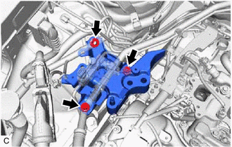
16. REMOVE ENGINE MOUNTING INSULATOR SUB-ASSEMBLY RH
(a) Remove the bolt and separate the cooler bracket from the engine mounting insulator sub-assembly RH.
| (b) Remove the 2 bolts and 2 nuts and separate the engine mounting insulator sub-assembly RH from the front No. 1 engine mounting bracket LH. |
|
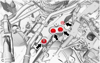
| (c) Remove the 2 bolts, nut and engine mounting insulator sub-assembly RH. |
|
17. REMOVE ENGINE MOUNTING SPACER
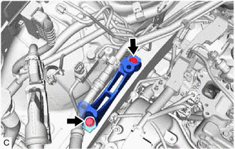
(a) Remove the 2 bolts and engine mounting spacer.
18. DISCONNECT ENGINE WIRE
| (a) Disconnect the water inlet with thermostat sub-assembly connector. |
|
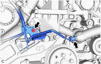
(b) Remove the bolt to disconnect the engine wire.
19. REMOVE FRONT NO. 1 ENGINE MOUNTING BRACKET LH
Click here
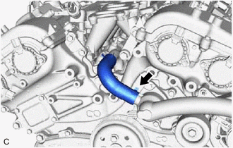
20. DISCONNECT NO. 2 RADIATOR HOSE
| (a) Slide the clip and disconnect the No. 2 radiator hose. |
|
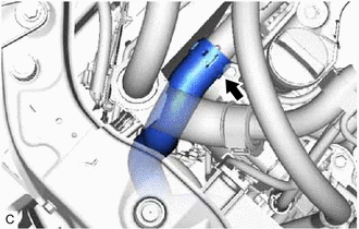
21. DISCONNECT WATER BY-PASS HOSE
| (a) Slide the clip and disconnect the water by-pass hose. |
|
22. REMOVE WATER INLET WITH THERMOSTAT SUB-ASSEMBLY
| (a) Remove the 2 bolts, 2 nuts and water inlet with thermostat sub-assembly. |
|
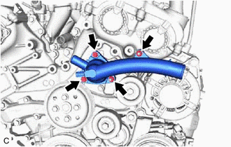
(b) Remove the gasket from the water inlet with thermostat sub-assembly.
 Installation
INSTALLATION PROCEDURE 1. INSTALL WATER INLET WITH THERMOSTAT SUB-ASSEMBLY (a) Install a new gasket to the water inlet with thermostat sub-assembly. (b) Install the water inlet with thermostat sub-ass ...
 Water Pump
...
Other materials:
Lexus RX (RX 350L, RX450h) 2016-2026 Repair Manual > Parking Assist Monitor System: Vehicle Information Unmatched (C168D)
DESCRIPTION This DTC is stored if the rear television camera assembly judges as a result of its self check that the vehicle information received from the main body ECU (multiplex network body ECU) via CAN communication and the vehicle information stored in the rear television camera assembly do not ...
Lexus RX (RX 350L, RX450h) 2016-2026 Repair Manual > 4wd Control Switch: Removal
REMOVAL PROCEDURE 1. REMOVE REAR CONSOLE UPPER PANEL Click here 2. REMOVE LOWER NO. 2 INSTRUMENT PANEL FINISH PANEL Click here 3. REMOVE LOWER NO. 1 INSTRUMENT PANEL FINISH PANEL Click here 4. REMOVE SHIFT LEVER KNOB SUB-ASSEMBLY Click here 5. REMOVE INSTRUMENT CLUSTER FINISH PANEL ORNAMENT ...
Lexus RX (RX 350L, RX450h) 2016-{YEAR} Owners Manual
- For your information
- Pictorial index
- For safety and security
- Instrument cluster
- Operation of each component
- Driving
- Lexus Display Audio system
- Interior features
- Maintenance and care
- When trouble arises
- Vehicle specifications
- For owners
Lexus RX (RX 350L, RX450h) 2016-{YEAR} Repair Manual

0.0109