Lexus RX (RX 350L, RX450h) 2016-2026 Repair Manual: Disassembly
DISASSEMBLY
CAUTION / NOTICE / HINT
HINT:
- Use the same procedure for the RH side and LH side.
- The following procedure is for the LH side.
PROCEDURE
1. REMOVE OUTER MIRROR
Click here .gif)
2. REMOVE NO. 1 OUTER MIRROR COVER
Click here
3. REMOVE NO. 2 OUTER MIRROR COVER
| (a) Remove the screw. |
|
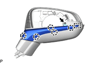
(b) Disengage the 5 claws and guide to remove the No. 2 outer mirror cover.
4. REMOVE OUTER MIRROR HOLE COVER
(a) w/ Panoramic View Monitor System:
| (1) Disengage the clamp. |
|
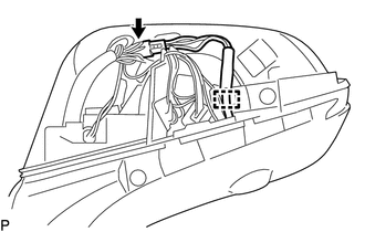
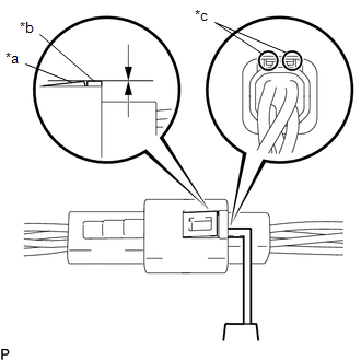
| (2) Insert a 0.9 mm (0.0354 in.) spark plug gap gauge or similar tool into the connector as shown in the illustration. Lift the claw and disconnect the connector. NOTICE:
|
|
| (b) Remove the screw. |
|
(c) Disengage the 3 claws and 2 guides to remove the outer mirror hole cover.
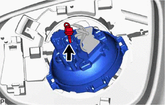
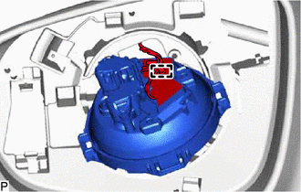
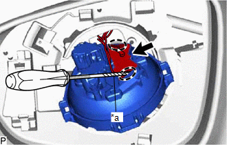
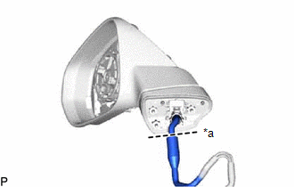
5. REMOVE SIDE TURN SIGNAL LIGHT ASSEMBLY
Click here
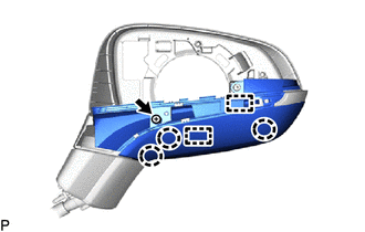
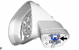
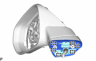
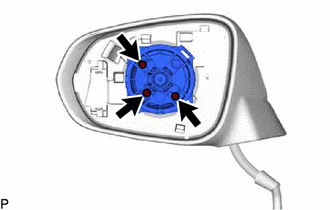
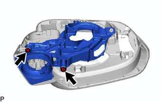
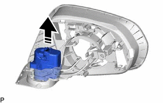
6. REMOVE OUTER MIRROR ACTUATOR ASSEMBLY (for TMMC Made)
| (a) Remove the 3 screws. |
|
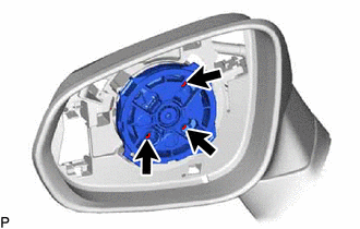
(b) Disengage the guide as shown in the illustration.
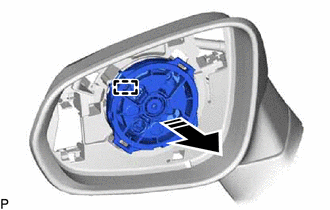
.png) | Remove in this Direction |
| (c) Disengage the clamp. |
|
| (d) Remove the connector cover. |
|
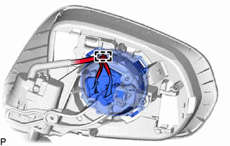
| (e) Disconnect the connector. |
|
| (f) Disengage the clamp. |
|
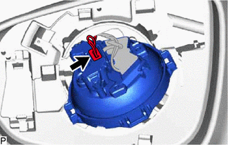
(g) Using a screwdriver with its tip wrapped with protective tape, disconnect the connector as shown in the illustration to remove the outer mirror actuator assembly.
NOTICE:
Be careful not to bend the terminals of the connector.
| *a | Protective Tape |
.png) | Insert Screwdriver Here |
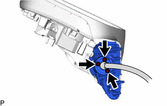
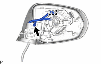
7. REMOVE OUTER MIRROR RETRACTOR LH (w/ Power Retract Mirror)
| (a) Cut the wire harness sub-assembly at the position shown in the illustration. |
|
(b) Remove the vinyl tape.
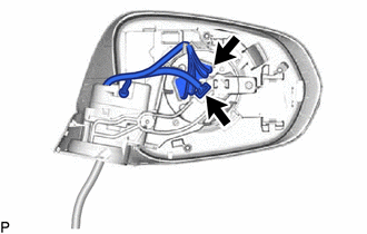
| (c) Remove the screw. |
|
(d) Disengage the 2 claws and 2 guides to remove the clamp.
| (e) Disengage the 6 guides and remove the gasket sub-assembly. NOTICE: Make sure to replace the gasket sub-assembly with a new one. |
|
| (f) Using a T25 "TORX" socket wrench, remove the 3 screws. NOTICE: Make sure to replace the screw with a new one. |
|
(g) Remove the base sub-assembly as shown in the illustration.
| | Remove in this Direction |
| (h) Remove the 3 screws. |
|
| (i) Disconnect the connector. |
|
(j) Disengage the clamp.
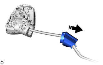
| (k) Disconnect the 2 connectors to remove the actuator sub-assembly. |
|
(l) Pull the wire harness sub-assembly through the frame sub-assembly as shown in the illustration to remove the wire harness sub-assembly.
NOTICE:
Make sure to replace the wire harness sub-assembly with a new one.
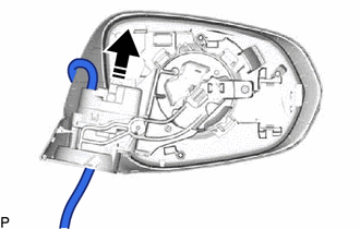
| | Remove in this Direction |
| (m) Remove the 2 screws. |
|
(n) Remove the frame sub-assembly from the support as shown in the illustration.
NOTICE:
Make sure to replace the frame sub-assembly with a new one.
| | Remove in this Direction |
 Inspection
INSPECTION PROCEDURE 1. INSPECT OUTER REAR VIEW MIRROR ASSEMBLY RH (a) Check the operation of the mirror surface. NOTICE: If the mirror surface is fully turned to the right, left, upward or downward p ...
 Installation
INSTALLATION CAUTION / NOTICE / HINT HINT:
Use the same procedure for the RH side and LH side.
The following procedure is for the LH side.
PROCEDURE 1. INSTALL OUTER REAR VIEW MIRROR ASSEMBLY ...
Other materials:
Lexus RX (RX 350L, RX450h) 2016-2026 Repair Manual > Brake Master Cylinder: Inspection
INSPECTION PROCEDURE 1. INSPECT AND ADJUST BRAKE BOOSTER PUSH ROD NOTICE: Make the adjustment with no vacuum in the brake booster assembly. (Depress the brake pedal several times with the engine stopped.) HINT:
Adjustment of the brake booster push rod is required when the brake master cylinder su ...
Lexus RX (RX 350L, RX450h) 2016-2026 Repair Manual > Vehicle Stability Control System: Left Rear Wheel Speed Sensor Supply Voltage Circuit Short to Ground or Open (C14E614,C14E914)
DESCRIPTION Refer to DTC C050C1F. Click here DTC No. Detection Item DTC Detection Condition Trouble Area C14E614 Left Rear Wheel Speed Sensor Supply Voltage Circuit Short to Ground or Open With the +BS terminal voltage 9.5 to 17.4 V, the sensor power supply voltage decreases for 0 ...
Lexus RX (RX 350L, RX450h) 2016-{YEAR} Owners Manual
- For your information
- Pictorial index
- For safety and security
- Instrument cluster
- Operation of each component
- Driving
- Lexus Display Audio system
- Interior features
- Maintenance and care
- When trouble arises
- Vehicle specifications
- For owners
Lexus RX (RX 350L, RX450h) 2016-{YEAR} Repair Manual

0.0125