Lexus RX (RX 350L, RX450h) 2016-2026 Repair Manual: Terminals Of Ecu
TERMINALS OF ECU
CHECK OUTER MIRROR CONTROL ECU ASSEMBLY (DRIVER DOOR)
.png)
(a) Disconnect the N4 outer mirror control ECU assembly (driver door) connector.
(b) Measure the voltage and resistance according to the value(s) in the table below.
HINT:
Measure the values on the wire harness side with the connector disconnected.
| Terminal No. (Symbol) | Wiring Color | Terminal Description | Condition | Specified Condition |
|---|---|---|---|---|
| N4-14 (BDR) - Body ground | L - Body ground | +B power supply | Always | 11 to 14 V |
| N4-6 (CPUB) - Body ground | L - Body ground | +B power supply | Always | 11 to 14 V |
| N4-5 (SIG) - Body ground | Y - Body ground | Ignition power supply | Engine switch off → on (IG) | Below 1 V → 11 to 14 V |
| N4-7 (GND) - Body ground | W-B - Body ground | Ground | Always | Below 1 Ω |
(c) Reconnect the N4 outer mirror control ECU assembly (driver door) connector.
(d) Measure the voltage according to the value(s) in the table below.
| Terminal No. (Symbol) | Wiring Color | Terminal Description | Condition | Specified Condition |
|---|---|---|---|---|
| z12-3 (MR) - Body ground | SB - Body ground | Power retract mirror motor drive voltage | Outer rear view mirror assembly (driver door) being retracted | 11 to 14 V |
| Outer rear view mirror assembly (driver door) stopped | Below 1 V | |||
| z12-11 (MF) - Body ground | LG - Body ground | Power retract mirror motor drive voltage | Outer rear view mirror assembly (driver door) returning | 11 to 14 V |
| Outer rear view mirror assembly (driver door) stopped | Below 1 V | |||
| z12-1 (MV) - z12-10 (M+) | V - R | Vertical mirror motor drive voltage | Driver door mirror surface moving upward → stopped | 11 to 14 V → Below 1 V |
| z12-10 (M+) - z12-1 (MV) | R - V | Vertical mirror motor drive voltage | Driver door mirror surface moving downward → stopped | 11 to 14 V → Below 1 V |
| z12-10 (M+) - z12-9 (MH) | R - BR | Horizontal mirror motor drive voltage | Driver door mirror surface moving right → stopped | 11 to 14 V → Below 1 V |
| z12-9 (MH) - z12-10 (M+) | BR - R | Horizontal mirror motor drive voltage | Driver door mirror surface moving left → stopped | 11 to 14 V → Below 1 V |
| z12-4 (HTR+) - z12-12 (TRN-) | B-G - W | Mirror heater relay drive voltage | Mirror heater switch (rear window defogger switch) on | 11 to 14 V |
| z12-5 (VDD) - N4-7 (GND) | O - W-B | Mirror position sensor power supply | Engine switch on (IG) | 4.75 to 5.25 V |
| z12-6 (VSSR) - N4-7 (GND) | W-B - W-B | Mirror position sensor signal | Engine switch on (IG) | 0 to 5 V |
| z12-13 (HSSR) - N4-7 (GND) | Y-B - W-B | Mirror position sensor signal | Engine switch on (IG) | 0 to 5 V |
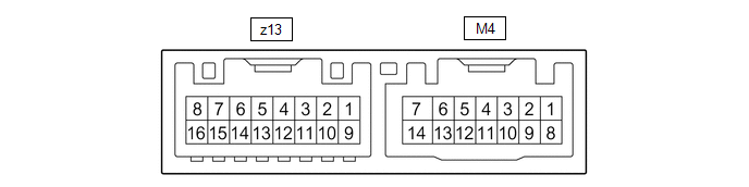
CHECK OUTER MIRROR CONTROL ECU ASSEMBLY (FRONT PASSENGER DOOR)
(a) Disconnect the M4 outer mirror control ECU assembly (front passenger door) connector.
(b) Measure the voltage and resistance according to the value(s) in the table below.
HINT:
Measure the values on the wire harness side with the connector disconnected.
| Terminal No. (Symbol) | Wiring Color | Terminal Description | Condition | Specified Condition |
|---|---|---|---|---|
| M4-14 (BDR) - Body ground | G - Body ground | +B power supply | Always | 11 to 14 V |
| M4-6 (CPUB) - Body ground | GR - Body ground | +B power supply | Always | 11 to 14 V |
| M4-5 (SIG) - Body ground | B - Body ground | Ignition power supply | Engine switch off → on (IG) | Below 1 V → 11 to 14 V |
| M4-7 (GND) - Body ground | W-B - Body ground | Ground | Always | Below 1 Ω |
(c) Reconnect the M4 outer mirror control ECU assembly (front passenger door) connector.
(d) Measure the voltage according to the value(s) in the table below.
| Terminal No. (Symbol) | Wiring Color | Terminal Description | Condition | Specified Condition |
|---|---|---|---|---|
| z13-3 (MR) - Body ground | SB - Body ground | Power retract mirror motor drive voltage | Outer rear view mirror assembly (front passenger door) being retracted | 11 to 14 V |
| Outer rear view mirror assembly (front passenger door) stopped | Below 1 V | |||
| z13-11 (MF) - Body ground | LG - Body ground | Power retract mirror motor drive voltage | Outer rear view mirror assembly (front passenger door) returning | 11 to 14 V |
| Outer rear view mirror assembly (front passenger door) stopped | Below 1 V | |||
| z13-1 (MV) - z13-10 (M+) | V - R | Vertical mirror motor drive voltage | Front passenger door mirror surface moving upward → stopped | 11 to 14 V → Below 1 V |
| z13-10 (M+) - z13-1 (MV) | R - V | Vertical mirror motor drive voltage | Front passenger door mirror surface moving downward → stopped | 11 to 14 V → Below 1 V |
| z13-10 (M+) - z13-9 (MH) | R - BR | Horizontal mirror motor drive voltage | Front passenger door mirror surface moving right → stopped | 11 to 14 V → Below 1 V |
| z13-9 (MH) - z13-10 (M+) | BR - R | Horizontal mirror motor drive voltage | Front passenger door mirror surface moving left → stopped | 11 to 14 V → Below 1 V |
| z13-4 (HTR+) - z13-12 (TRN-) | B-G - W | Mirror heater relay drive voltage | Mirror heater switch (rear window defogger switch) on | 11 to 14 V |
| z13-5 (VDD) - M4-7 (GND) | O - W-B | Mirror position sensor power supply | Engine switch on (IG) | 4.75 to 5.25 V |
| z13-6 (VSSR) - M4-7 (GND) | W-B - W-B | Mirror position sensor signal | Engine switch on (IG) | 0 to 5 V |
| z13-13 (HSSR) - M4-7 (GND) | Y-B - W-B | Mirror position sensor signal | Engine switch on (IG) | 0 to 5 V |
 Problem Symptoms Table
PROBLEM SYMPTOMS TABLE NOTICE: If the battery voltage is low, the mirror heater function may not operate. When "Operation of Electrical Items Restricted." is displayed on the multi-information display ...
 Diagnosis System
DIAGNOSIS SYSTEM CHECK DLC3 (a) Check the DLC3. Click here INSPECT BATTERY VOLTAGE (a) Measure the battery voltage. Standard Voltage: 11 to 14 V If the voltage is below 11 V, recharge or replace th ...
Other materials:
Lexus RX (RX 350L, RX450h) 2016-2026 Repair Manual > Oil Pump: Inspection
INSPECTION PROCEDURE 1. INSPECT FRONT OIL PUMP BODY SUB-ASSEMBLY (a) Turn the front oil pump drive gear with 2 screwdrivers and check that it rotates smoothly. NOTICE: Be careful not to damage the lip of the front oil pump oil seal. 2. INSPECT CLEARANCE OF FRONT OIL PUMP BODY AND GEAR ...
Lexus RX (RX 350L, RX450h) 2016-2026 Repair Manual > Accelerator Pedal: On-vehicle Inspection
ON-VEHICLE INSPECTION PROCEDURE 1. INSPECT ACCELERATOR PEDAL SENSOR ASSEMBLY (a) Connect the Techstream to the DLC3. (b) Turn the engine switch on (IG). (c) Turn the Techstream on. (d) Enter the following menus: Powertrain / Engine / Data List / Accelerator Position Sensor No. 1 Voltage and Accelera ...
Lexus RX (RX 350L, RX450h) 2016-{YEAR} Owners Manual
- For your information
- Pictorial index
- For safety and security
- Instrument cluster
- Operation of each component
- Driving
- Lexus Display Audio system
- Interior features
- Maintenance and care
- When trouble arises
- Vehicle specifications
- For owners
Lexus RX (RX 350L, RX450h) 2016-{YEAR} Repair Manual

0.0113