Lexus RX (RX 350L, RX450h) 2016-2026 Repair Manual: Installation
INSTALLATION
PROCEDURE
1. INSTALL SLIDING ROOF HOUSING ASSEMBLY
(a) Loosen the 10 bolts of the brackets of the sliding roof housing assembly.
(b) Temporarily install the sliding roof housing assembly with the 6 nuts and 8 bolts.
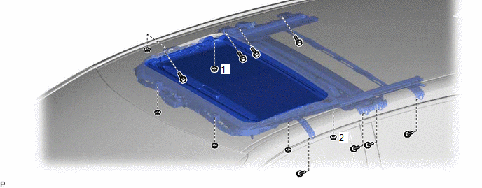
(c) Tighten the 2 nuts.
HINT:
Tighten the 2 nuts in the order shown in the illustration.
Torque:
5.5 N·m {56 kgf·cm, 49 in·lbf}
(d) Tighten the 4 nuts.
Torque:
5.5 N·m {56 kgf·cm, 49 in·lbf}
(e) Tighten the 18 bolts to install the sliding roof housing assembly.
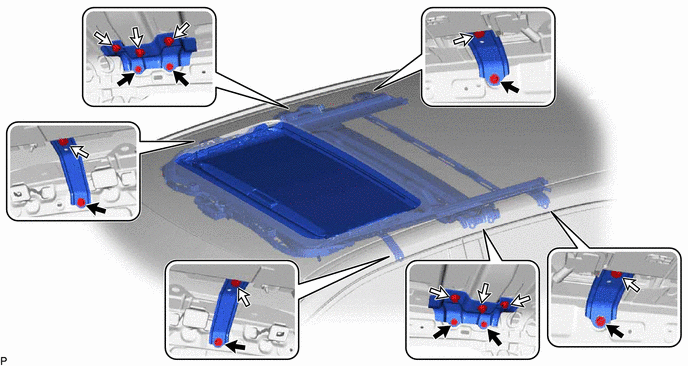
.png) | Bolt (A) | .png) | Bolt (B) |
HINT:
The brackets can be installed in any order. The bolts must be tightened in the order of (A) then (B).
Torque:
8.0 N·m {82 kgf·cm, 71 in·lbf}
2. CONNECT SLIDING ROOF DRAIN HOSE
| (a) for Clamp Type: (1) Connect the sliding roof drain hose. HINT: Slide the hose to the base of the drain pipe. (2) Engage the claw to secure the sliding roof drain hose. HINT:
|
|
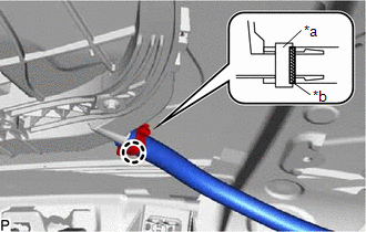
(b) for Clip Type:
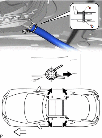
| *a | Clip |
| *b | Marking |
| | Outside |
| | Front Side |
(1) Expand the clip and connect the sliding roof drain hose.
HINT:
Slide the hose to the base of the drain pipe.
(2) Release the clip to secure the sliding roof drain hose.
NOTICE:
The clip must face toward the outside of the vehicle and also be above the lower surface of the sliding roof housing assembly when installing the sliding roof drain hose.
HINT:
- Make sure that the clip is on the marking or between the marking and hose end.
- Use the same procedure for the other 3 sliding roof drain hoses.
3. INSTALL SLIDING ROOF WEATHERSTRIP (for TMMC Made)
(a) Install the sliding roof weatherstrip.
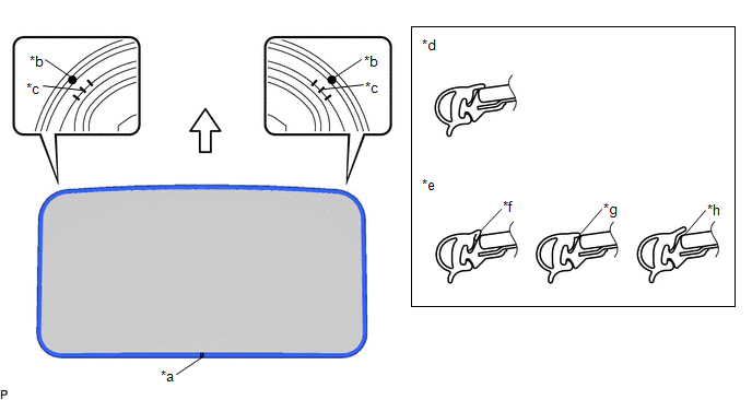
| *a | Joint | *b | Alignment Mark |
| *c | Middle Mark | *d | Correct |
| *e | Incorrect | *f | Pinched |
| *g | Exposed | *h | Gap (raised, wavy, etc.) |
| | Front Side | - | - |
(1) Position the joint of the sliding roof weatherstrip on the rear side.
(2) Align the alignment marks on the sliding roof weatherstrip with the middle marks on the front corners of the sliding roof panel sub-assembly and install the sliding roof weatherstrip.
(3) Install the lip of the sliding roof weatherstrip securely.
4. INSTALL SLIDING ROOF GLASS SUB-ASSEMBLY
(a) Using a T25 "TORX" socket wrench, temporarily install the sliding roof glass sub-assembly with the 4 screws.
(b) Perform a level check.
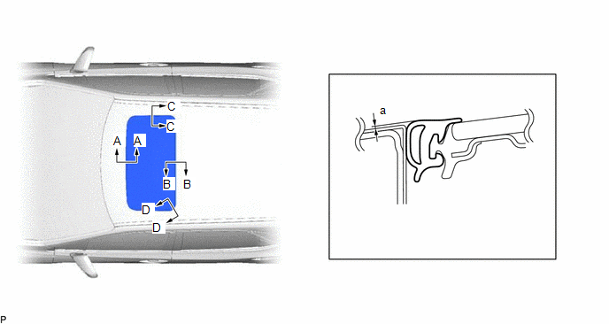
(1) Check the difference in level "a" between the roof panel and the upper surface of the sliding roof weatherstrip when the sliding roof glass sub-assembly is fully closed.
HINT:
"+" represents the condition that the glass is above the panel level. "-" represents the condition that the glass is below the panel level.
Standard:
| Area | Measurement | Area | Measurement |
|---|---|---|---|
| A - A | 0 + 1.0 mm (0 + 0.0394 in.) 0 - 2.0 mm (0 - 0.0787 in.) | B - B | 0 + 2.0 mm (0 + 0.0787 in.) 0 - 1.0 mm (0 - 0.0394 in.) |
| C - C | 0 + 1.5 mm (0 + 0.0591 in.) 0 - 1.5 mm (0 - 0.0591 in.) | D - D | 0 + 1.5 mm (0 + 0.0591 in.) 0 - 1.0 mm (0 - 0.0394 in.) |
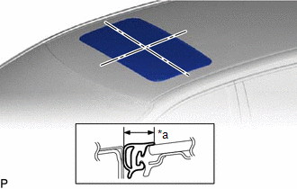
| (c) Perform a gap check. (1) Check the gap between the roof panel and sliding roof glass sub-assembly. NOTICE: The gap must be even all around. |
|
(d) After adjusting the sliding roof glass sub-assembly, using a T25 "TORX" socket wrench, install the sliding roof glass sub-assembly with the 4 screws.
Torque:
4.0 N·m {41 kgf·cm, 35 in·lbf}
5. CHECK FOR WATER LEAK
(a) After adjusting the sliding roof glass sub-assembly, check for water leakage into the vehicle interior.
(b) If there are any leaks, readjust the sliding roof glass sub-assembly.
6. INSTALL CURTAIN SHIELD AIRBAG ASSEMBLY LH (w/o Rear No.2 Seat)
Click here .gif)
7. INSTALL CURTAIN SHIELD AIRBAG ASSEMBLY LH (w/ Rear No.2 Seat)
Click here
8. INSTALL CURTAIN SHIELD AIRBAG ASSEMBLY RH
HINT:
Use the same procedure as for the LH side.
9. INSTALL SLIDING ROOF SIDE GARNISH LH
(a) Engage the 2 claws to install a new sliding roof side garnish LH.
10. INSTALL SLIDING ROOF SIDE GARNISH RH
HINT:
Use the same procedure as for the LH side.
11. INSTALL SLIDING ROOF DRIVE GEAR SUB-ASSEMBLY
HINT:
Perform this procedure only when replacement of the sliding roof drive gear sub-assembly is necessary.
(a) Apply MP grease to the gear of the sliding roof drive gear sub-assembly.
(b) Install the sliding roof drive gear sub-assembly with the 2 bolts.
Torque:
5.4 N·m {55 kgf·cm, 48 in·lbf}
(c) Connect the connector.
(d) Engage the 2 guides as shown in the illustration.
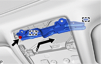
.png) | Install in this Direction |
(e) Install the map light bracket with the bolt.
Torque:
5.4 N·m {55 kgf·cm, 48 in·lbf}
(f) Install the map light assembly.
Click here
12. INITIALIZE SLIDING ROOF SYSTEM
Click here
13. CHECK SLIDING ROOF SYSTEM
Click here
 Disassembly
DISASSEMBLY PROCEDURE 1. REMOVE SLIDING ROOF DRIVE GEAR SUB-ASSEMBLY (a) Remove the bolt. Remove in this Direction (b) Disengage the 2 guides as shown in the illustration to remove the map l ...
 Reassembly
REASSEMBLY PROCEDURE 1. INSTALL SLIDING ROOF DRIVE CABLE SUB-ASSEMBLY (a) Hold down the roof wind deflector panel sub-assembly. Hold Position (b) Using a screwdriver, slide the sliding roof ...
Other materials:
Lexus RX (RX 350L, RX450h) 2016-2026 Repair Manual > Smart Access System With Push-button Start (for Entry Function): System Diagram
SYSTEM DIAGRAM
This is a detailed diagram related to the certification ECU (smart key ECU assembly).
This is a detailed diagram related to the main body ECU (multiplex network body ECU). Component Function Front door outside handle assembly Receives request signals from ...
Lexus RX (RX 350L, RX450h) 2016-2026 Repair Manual > Engine Coolant Temperature Sensor: Installation
INSTALLATION PROCEDURE 1. INSTALL ENGINE COOLANT TEMPERATURE SENSOR HINT: Perform "Inspection After Repair" after replacing the engine coolant temperature sensor. Click here (a) Apply a light coat of engine coolant to the O-ring of the engine coolant temperature sensor. NOTICE: If reusing the eng ...
Lexus RX (RX 350L, RX450h) 2016-{YEAR} Owners Manual
- For your information
- Pictorial index
- For safety and security
- Instrument cluster
- Operation of each component
- Driving
- Lexus Display Audio system
- Interior features
- Maintenance and care
- When trouble arises
- Vehicle specifications
- For owners
Lexus RX (RX 350L, RX450h) 2016-{YEAR} Repair Manual

0.0096