Lexus RX (RX 350L, RX450h) 2016-2026 Repair Manual: Sliding Roof does not Move by Operating Sliding Roof Control Switch
DESCRIPTION
The sliding roof ECU (sliding roof drive gear sub-assembly) receives slide and tilt signals and operates its built-in motor when the sliding roof switch (map light assembly) is operated.
WIRING DIAGRAM
Click here .gif)
CAUTION / NOTICE / HINT
NOTICE:
- Inspect the fuses for circuits related to this system before performing the following procedure.
-
If the sliding roof ECU (sliding roof drive gear sub-assembly) is removed and reinstalled or replaced, the sliding roof ECU (sliding roof drive gear sub-assembly) must be initialized.
Click here
-
The sliding roof system uses the LIN communication system. First, confirm that there are no malfunctions in the LIN communication system. Refer to How to Proceed with Troubleshooting.
Click here
-
If a sliding roof ECU (sliding roof drive gear sub-assembly) DTC is output, first perform troubleshooting for the sliding roof ECU (sliding roof drive gear sub-assembly) DTC.
Click here
PROCEDURE
| 1. | READ VALUE USING TECHSTREAM |
(a) Connect the Techstream to the DLC3.
(b) Turn the engine switch on (IG).
(c) Turn the Techstream on.
(d) Enter the following menus: Body Electrical / Sliding Roof / Data List.
(e) Read the Data List according to the display on the Techstream.
Body Electrical > Sliding Roof > Data List| Tester Display | Measurement Item | Range | Normal Condition | Diagnostic Note |
|---|---|---|---|---|
| Open Switch | OPEN switch signal | OFF or ON | OFF: OPEN switch not pressed ON: OPEN switch pressed | - |
| Close Switch | CLOSE switch signal | OFF or ON | OFF: CLOSE switch not pressed ON: CLOSE switch pressed | - |
| Up Switch | UP switch signal | OFF or ON | OFF: UP switch not pressed ON: UP switch pressed | - |
| Down Switch | DOWN switch signal | OFF or ON | OFF: DOWN switch not pressed ON: DOWN switch pressed | - |
| Tester Display |
|---|
| Open Switch |
| Close Switch |
| Up Switch |
| Down Switch |
OK:
The Techstream display changes according to the operation of each switch as shown in the table.
| NG | .gif) | GO TO STEP 5 |
|
.gif)
| 2. | CHECK HARNESS AND CONNECTOR (SLIDING ROOF ECU (SLIDING ROOF DRIVE GEAR SUB-ASSEMBLY) - BATTERY AND BODY GROUND) |
| (a) Disconnect the U2 sliding roof ECU (sliding roof drive gear sub-assembly) connector. |
|
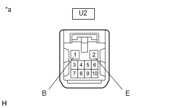
(b) Measure the voltage according to the value(s) in the table below.
Standard Voltage:
| Tester Connection | Condition | Specified Condition |
|---|---|---|
| U2-1 (B) - Body ground | Always | 11 to 14 V |
(c) Measure the resistance according to the value(s) in the table below.
Standard Resistance:
| Tester Connection | Condition | Specified Condition |
|---|---|---|
| U2-2 (E) - Body ground | Always | Below 1 Ω |
| NG | | REPAIR OR REPLACE HARNESS OR CONNECTOR |
|
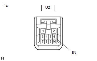
| 3. | CHECK HARNESS AND CONNECTOR (SLIDING ROOF ECU (SLIDING ROOF DRIVE GEAR SUB-ASSEMBLY) - IG POWER SUPPLY) |
| (a) Measure the voltage according to the value(s) in the table below. Standard Voltage:
|
|
| NG | | REPAIR OR REPLACE HARNESS OR CONNECTOR |
|
| 4. | INSPECT SLIDING ROOF SWITCH (MAP LIGHT ASSEMBLY) |
(a) Remove the sliding roof switch (map light assembly).
Click here
(b) Inspect the sliding roof switch (map light assembly).
Click here
| OK | | REPLACE SLIDING ROOF ECU (SLIDING ROOF DRIVE GEAR SUB-ASSEMBLY) |
| NG | | REPLACE SLIDING ROOF SWITCH (MAP LIGHT ASSEMBLY) |
| 5. | INSPECT SLIDING ROOF SWITCH (MAP LIGHT ASSEMBLY) |
(a) Remove the sliding roof switch (map light assembly).
Click here
(b) Inspect the sliding roof switch (map light assembly).
Click here
| NG | | REPLACE SLIDING ROOF SWITCH (MAP LIGHT ASSEMBLY) |
|
| 6. | CHECK HARNESS AND CONNECTOR (SLIDING ROOF ECU (SLIDING ROOF DRIVE GEAR SUB-ASSEMBLY) - SLIDING ROOF SWITCH (MAP LIGHT ASSEMBLY) AND BODY GROUND) |
(a) Disconnect the U11 sliding roof switch (map light assembly) connector.
(b) Disconnect the U2 sliding roof ECU (sliding roof drive gear sub-assembly) connector.
(c) Measure the resistance according to the value(s) in the table below.
Standard Resistance:
| Tester Connection | Condition | Specified Condition |
|---|---|---|
| U2-8 (CLS) - U11-12 (CLS) | Always | Below 1 Ω |
| U2-8 (CLS) or U11-12 (CLS) - Body ground | Always | 10 kΩ or higher |
| U2-10 (OPN) - U11-11 (OPN) | Always | Below 1 Ω |
| U2-10 (OPN) or U11-11 (OPN) - Body ground | Always | 10 kΩ or higher |
| U2-9 (CLS) - U11-24 (DOWN) | Always | Below 1 Ω |
| U2-9 (CLS) or U11-24 (DOWN) - Body ground | Always | 10 kΩ or higher |
| U2-5 (OPN) - U11-23 (UP) | Always | Below 1 Ω |
| U2-5 (OPN) or U11-23 (UP) - Body ground | Always | 10 kΩ or higher |
| U11-19 (GND) - Body ground | Always | Below 1 Ω |
| U2-2 (E) - Body ground | Always | Below 1 Ω |
| OK | | REPLACE SLIDING ROOF ECU (SLIDING ROOF DRIVE GEAR SUB-ASSEMBLY) |
| NG | | REPAIR OR REPLACE HARNESS OR CONNECTOR |
 Remote Control System does not Operate
DESCRIPTION The main body ECU (multiplex network body ECU) receives remote control signals from the driver door key cylinder or electrical key transmitter sub-assembly. Then, the main body ECU (multip ...
 Window / Glass
...
Other materials:
Lexus RX (RX 350L, RX450h) 2016-2026 Repair Manual > Headup Display System: How To Proceed With Troubleshooting
CAUTION / NOTICE / HINT HINT:
Use the following procedure to troubleshoot the headup display system.
*: Use the Techstream.
PROCEDURE 1. VEHICLE BROUGHT TO WORKSHOP
NEXT 2. CUSTOMER PROBLEM ANALYSIS
NEXT 3. INSPECT BATTERY VOLTAGE ...
Lexus RX (RX 350L, RX450h) 2016-2026 Repair Manual > Cylinder Head Gasket: Removal
REMOVAL CAUTION / NOTICE / HINT The necessary procedures (adjustment, calibration, initialization, or registration) that must be performed after parts are removed and installed, or replaced during engine unit removal/installation are shown below. Necessary Procedure After Parts Removed/Installed/Rep ...
Lexus RX (RX 350L, RX450h) 2016-{YEAR} Owners Manual
- For your information
- Pictorial index
- For safety and security
- Instrument cluster
- Operation of each component
- Driving
- Lexus Display Audio system
- Interior features
- Maintenance and care
- When trouble arises
- Vehicle specifications
- For owners
Lexus RX (RX 350L, RX450h) 2016-{YEAR} Repair Manual

0.0121