Lexus RX (RX 350L, RX450h) 2016-2026 Repair Manual: Removal
REMOVAL
CAUTION / NOTICE / HINT
The necessary procedures (adjustment, calibration, initialization or registration) that must be performed after parts are removed, installed or replaced during the rear door lock assembly removal/installation are shown below.
Necessary Procedures After Parts Removed/Installed/Replaced| Replaced Part or Performed Procedure | Necessary Procedure | Effect/Inoperative Function when Necessary Procedure not Performed | Link |
|---|---|---|---|
|
*1: When performing learning using the Techstream.
Click here | |||
| Disconnect cable from negative battery terminal | Memorize steering angle neutral point | Lane Control System | |
| Pre-collision system | |||
| Intelligent Clearance Sonar System*1 | |||
| Lighting System (w/ Automatic Headlight Beam Level Control System) | | ||
| Parking Assist Monitor System | | ||
| Panoramic View Monitor System | | ||
| Initialize back door lock | Power Door Lock Control System | | |
| Reset back door close position | Power Back Door System (w/ Outside Door Control Switch) | | |
| Initialize Power Window Control System |
| |
HINT:
- Use the same procedure for the RH side and LH side.
- The following procedure is for the LH side.
PROCEDURE
1. PRECAUTION
NOTICE:
After turning the engine switch off, waiting time may be required before disconnecting the cable from the negative (-) battery terminal. Therefore, make sure to read the disconnecting the cable from the negative (-) battery terminal notices before proceeding with work.
Click here .gif)
2. DISCONNECT CABLE FROM NEGATIVE BATTERY TERMINAL
NOTICE:
When disconnecting the cable, some systems need to be initialized after the cable is reconnected.
Click here
3. REMOVE REAR DOOR INSIDE HANDLE BEZEL PLUG
Click here
4. REMOVE REAR POWER WINDOW REGULATOR SWITCH ASSEMBLY WITH REAR DOOR UPPER ARMREST BASE PANEL
Click here
5. REMOVE REAR DOOR ARMREST COVER
Click here
6. REMOVE COURTESY LIGHT ASSEMBLY
Click here
7. REMOVE REAR DOOR TRIM BOARD SUB-ASSEMBLY
Click here
8. REMOVE REAR DOOR INNER GLASS WEATHERSTRIP
Click here
9. REMOVE REAR DOOR NO. 2 TRIM BRACKET
Click here
10. REMOVE REAR DOOR SERVICE HOLE COVER
Click here
11. REMOVE REAR DOOR GLASS RUN
Click here
12. REMOVE REAR DOOR WINDOW DIVISION BAR SUB-ASSEMBLY
Click here
13. DISCONNECT REAR DOOR WEATHERSTRIP
(a) Disconnect the rear door weatherstrip until the screws of the rear door rear guide seal is visible.
14. REMOVE REAR DOOR REAR GUIDE SEAL
Click here
15. REMOVE REAR DOOR GLASS SUB-ASSEMBLY
Click here
16. REMOVE REAR DOOR LOCK ASSEMBLY
(a) Using a T30 "TORX" socket wrench, remove the 3 screws.
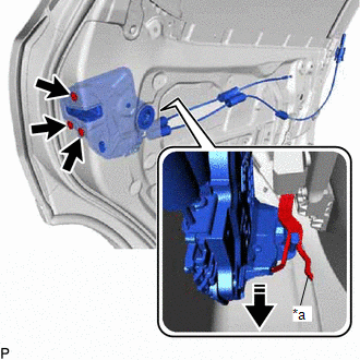
| *a | Release Plate |
.png) | Remove in this Direction |
(b) Move the rear door lock assembly downward to disconnect it from the release plate of the rear door outside handle frame sub-assembly, and remove the rear door lock assembly.
(c) When reusing the rear door lock assembly:
| (1) Remove the door lock wiring harness seal from the rear door lock assembly. |
|
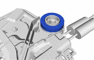
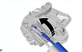
17. REMOVE REAR DOOR LOCK COVER SUB-ASSEMBLY
| (a) Using a screwdriver, disengage the 2 claws as shown in the illustration. |
|
(b) Disengage the 2 claws to remove the rear door lock cover sub-assembly as shown in the illustration.
| | Remove in this Direction |
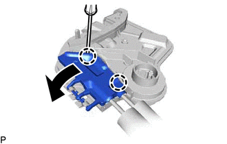
18. REMOVE REAR DOOR LOCK REMOTE CONTROL CABLE ASSEMBLY
(a) Remove the rear door lock remote control cable assembly as shown in the illustration.
| | Remove in this Direction |
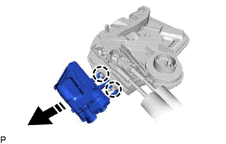
19. REMOVE REAR DOOR INSIDE LOCKING CABLE ASSEMBLY
(a) Remove the rear door inside locking cable assembly as shown in the illustration.
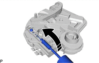
| | Remove in this Direction |
 Installation
INSTALLATION CAUTION / NOTICE / HINT HINT:
Use the same procedure for the RH side and LH side.
The following procedure is for the LH side.
PROCEDURE 1. PRECAUTION NOTICE: After turning the eng ...
 Transmitter Battery
ReplacementREPLACEMENT PROCEDURE 1. REMOVE TRANSMITTER BATTERY NOTICE: Take extra care when handling these precision electronic components. (a) Push the release hook knob and remove the mechanical key ...
Other materials:
Lexus RX (RX 350L, RX450h) 2016-2026 Repair Manual > Audio And Visual System (for 12.3 Inch Display): Sending Malfunction (Navigation to APGS) (U0073,U0100,U0129,U0140,U0155,U0164,U023B,U0265,U1110)
DESCRIPTION These DTCs are stored when a malfunction occurs in the CAN communication circuit. DTC No. Detection Item DTC Detection Condition Trouble Area U0073 Sending Malfunction (Navigation to APGS) CAN bus connection error CAN communication system U0100 Engine ECU Communi ...
Lexus RX (RX 350L, RX450h) 2016-2026 Repair Manual > Safety Connect System: Indicator (Red) Circuit Short to Ground (B157011,B157013)
DESCRIPTION This DTC is stored when the DCM (telematics transceiver) detects an open or short in the manual (SOS) switch red indicator circuit of the manual (SOS) switch. The manual (SOS) switch red indicator illuminates for 2 seconds and goes off when the engine switch is turned on (IG). If a malfu ...
Lexus RX (RX 350L, RX450h) 2016-{YEAR} Owners Manual
- For your information
- Pictorial index
- For safety and security
- Instrument cluster
- Operation of each component
- Driving
- Lexus Display Audio system
- Interior features
- Maintenance and care
- When trouble arises
- Vehicle specifications
- For owners
Lexus RX (RX 350L, RX450h) 2016-{YEAR} Repair Manual

0.0132