Lexus RX (RX 350L, RX450h) 2016-2026 Repair Manual: Installation
INSTALLATION
PROCEDURE
1. ADJUST COMPRESSOR OIL
(a) When replacing the compressor and magnetic clutch with a new one:
| (1) Remove the drain bolt (seal washer) from a new compressor and magnetic clutch. |
|
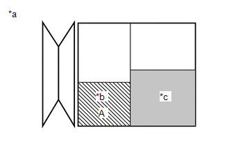
| (2) Gradually discharge the inert gas from the service valve of the new compressor and magnetic clutch. Then drain the following amount of oil from the new compressor before installation so that the amount of oil contained in it is the same as that in the compressor to be replaced. HINT: New compressors are filled with sufficient oil for the whole air conditioning system. Therefore, it is necessary to drain oil from the new compressor to compensate for oil remaining in the condenser and cooling unit. Standard (w/o Rear Air Conditioning System): (The amount of compressor oil inside a new compressor and magnetic clutch: 70 (+15) cc (2.37 (+0.51) fl.oz)) - (The amount of compressor oil remaining in the removed compressor and magnetic clutch) = The amount of compressor oil to be removed when replacing the compressor and magnetic clutch. Standard (w/ Rear Air Conditioning System): (The amount of compressor oil inside a new compressor and magnetic clutch: 120 (+15) cc (4.06 (+0.51) fl.oz)) - (The amount of compressor oil remaining in the removed compressor and magnetic clutch) = The amount of compressor oil to be removed when replacing the compressor and magnetic clutch. NOTICE:
|
|
(3) Install the drain bolt (seal washer).
Torque:
30 N·m {306 kgf·cm, 22 ft·lbf}
(b) If draining the oil is difficult, drain the oil using the following procedure:
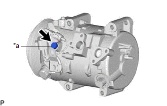
(1) Remove the suction seal cap.
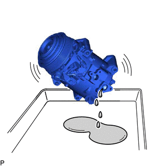
| (2) Lightly shake the compressor and magnetic clutch with the suction port facing down, and drain the oil (*1). NOTICE: Do not allow the pulley to come into contact with the compressor oil. |
|
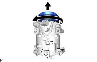
| (c) With the pulley facing down, rotate the pully as shown in the illustration 10 times at a rate of approximately once every 2 seconds (*2). CAUTION: If the pulley is rotated, refrigerant or oil may spray out. Thus, keep your face away from the compressor port. |
|
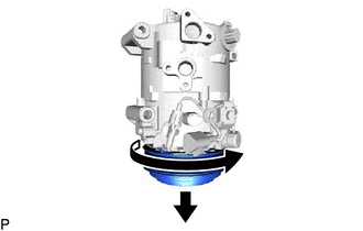
| (d) Rotate the pully once as shown in the illustration while quickly turning the compressor up (*3). |
|
(e) Perform step (*1) and drain the oil (*4).
(f) Drain the oil by repeating steps (*2) to (*4) approximately 5 times.
2. INSTALL COMPRESSOR AND MAGNETIC CLUTCH
(a) for Type A:
(1) Using an E8 "TORX" socket wrench, temporarily install the compressor and magnetic clutch with the 2 stud bolts.
Torque:
10 N·m {102 kgf·cm, 7 ft·lbf}
(2) Install the compressor and magnetic clutch and bracket with the 2 bolts and 2 nuts.
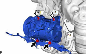
| *a | Bracket |
.png) | Bolt |
.png) | Nut |
Torque:
24.5 N·m {250 kgf·cm, 18 ft·lbf}
HINT:
Tighten the bolts and nuts in the order shown in the illustration to install the compressor and magnetic clutch.
(b) for Type B:
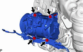
| (1) Install the compressor and magnetic clutch and bracket with the 4 bolts. Torque: 24.5 N·m {250 kgf·cm, 18 ft·lbf} HINT: Tighten the bolts in the order shown in the illustration to install the compressor and magnetic clutch. |
|
(c) Engage each clamp.
(d) Connect each connector.
3. CONNECT SUCTION HOSE SUB-ASSEMBLY
(a) Remove the vinyl tape from the suction hose sub-assembly.
(b) Sufficiently apply compressor oil to a new O-ring and the fitting surface of the suction hose sub-assembly.
Compressor Oil:
ND-OIL 12 or equivalent
(c) Install the O-ring to the suction hose sub-assembly.
(d) Install the suction hose sub-assembly to the compressor and magnetic clutch with the bolt.
Torque:
9.8 N·m {100 kgf·cm, 87 in·lbf}
4. CONNECT DISCHARGE HOSE SUB-ASSEMBLY
(a) Remove the vinyl tape from the discharge hose sub-assembly.
(b) Sufficiently apply compressor oil to a new O-ring and the fitting surface of the discharge hose sub-assembly.
Compressor Oil:
ND-OIL 12 or equivalent
(c) Install the O-ring to the discharge hose sub-assembly.
(d) Install the discharge hose sub-assembly to the compressor and magnetic clutch with the bolt.
Torque:
9.8 N·m {100 kgf·cm, 87 in·lbf}
5. INSTALL RADIATOR ASSEMBLY
Click here .gif)
6. INSTALL V-RIBBED BELT
Click here
7. CHARGE AIR CONDITIONING SYSTEM WITH REFRIGERANT
Click here
8. WARM UP ENGINE
Click here
9. INSPECT FOR REFRIGERANT LEAK
Click here
 Inspection
INSPECTION PROCEDURE 1. INSPECT COOLER COMPRESSOR ASSEMBLY (A/C LOCK SENSOR) (a) Measure the resistance according to the value(s) in the table below. Standard Resistance: Tester Connection Co ...
 Reassembly
REASSEMBLY PROCEDURE 1. INSTALL MAGNET CLUTCH ASSEMBLY (a) Secure the compressor and magnetic clutch in a vise between aluminum plates. (b) Install the magnet clutch stator with the parts aligned a ...
Other materials:
Lexus RX (RX 350L, RX450h) 2016-2026 Owners Manual > Other function: USB photo
Connecting a USB memory device enables you to enjoy photo on the Lexus
Display Audio display.
USB photo screen
Go to "USB Photo": "MENU" button → "Info" → "USB1 Photo" or "USB2
Photo"
Menu screen
Move the controller to the left to display the menu screen.
Change the full screen mode.
...
Lexus RX (RX 350L, RX450h) 2016-2026 Repair Manual > Power Seat Switch(for Rear Side): Inspection
INSPECTION PROCEDURE 1. INSPECT REAR POWER SEAT SWITCH LH (a) for LH Side: (1) Measure the resistance according to the value(s) in the table below. Standard Resistance: Tester Connection Condition Specified Condition 2 (FLDL) - 7 (E) FOLD switch pressed Below 100 Ω 2 (FLDL) - ...
Lexus RX (RX 350L, RX450h) 2016-{YEAR} Owners Manual
- For your information
- Pictorial index
- For safety and security
- Instrument cluster
- Operation of each component
- Driving
- Lexus Display Audio system
- Interior features
- Maintenance and care
- When trouble arises
- Vehicle specifications
- For owners
Lexus RX (RX 350L, RX450h) 2016-{YEAR} Repair Manual

0.0098