Lexus RX (RX 350L, RX450h) 2016-2026 Repair Manual: Installation
INSTALLATION
PROCEDURE
1. INSTALL COOLER CONDENSER ASSEMBLY
(a) Engage the 2 guides as shown in the illustration.
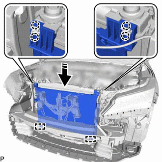
.png) | Install in this Direction |
NOTICE:
Do not damage the cooler condenser assembly or radiator assembly when installing the cooler condenser assembly.
(b) Engage the 4 claws to install the cooler condenser assembly.
HINT:
If a new cooler condenser assembly is installed, add compressor oil to the cooler condenser assembly as follows.
Capacity:
Add 40 cc (1.35 fl. oz)
Compressor Oil:
ND-OIL 12 or equivalent
2. CONNECT AIR CONDITIONER TUBE AND ACCESSORY ASSEMBLY
(a) Remove the vinyl tape from the air conditioner tube and accessory assembly and the connecting part of the cooler condenser assembly.
(b) Sufficiently apply compressor oil to a new O-ring and the fitting surface of the air conditioner tube and accessory assembly.
Compressor Oil:
ND-OIL 12 or equivalent
(c) Install the O-ring to the air conditioner tube and accessory assembly.
(d) Install the air conditioner tube and accessory assembly to the cooler condenser assembly with the bolt.
Torque:
5.4 N·m {55 kgf·cm, 48 in·lbf}
3. CONNECT DISCHARGE HOSE SUB-ASSEMBLY
(a) Remove the vinyl tape from the discharge hose sub-assembly and the connecting part of the cooler condenser assembly.
(b) Sufficiently apply compressor oil to a new O-ring and the fitting surface of the discharge hose sub-assembly.
Compressor Oil:
ND-OIL 12 or equivalent
(c) Install the O-ring to the discharge hose sub-assembly.
(d) Install the discharge hose sub-assembly to the cooler condenser assembly with the bolt.
Torque:
5.4 N·m {55 kgf·cm, 48 in·lbf}
4. INSTALL UPPER RADIATOR SUPPORT SUB-ASSEMBLY
Click here .gif)
5. INSTALL INLET AIR CLEANER ASSEMBLY
Click here
6. INSTALL HOOD LOCK ASSEMBLY
Click here
7. INSTALL HOOD LOCK RELEASE LEVER PROTECTOR
Click here
8. INSTALL HOOD LOCK CONTROL CABLE COVER
Click here
9. INSTALL FRONT BUMPER ASSEMBLY
Click here
10. CHARGE AIR CONDITIONING SYSTEM WITH REFRIGERANT
Click here
11. WARM UP ENGINE
Click here
12. INSPECT FOR REFRIGERANT LEAK
Click here
13. ADJUST HOOD SUB-ASSEMBLY
Click here
 Disassembly
DISASSEMBLY PROCEDURE 1. REMOVE COOLER DRYER (a) Using a 14 mm straight hexagon socket wrench, remove the cap from the modulator. *a Modulator (b) Using pliers, remove th ...
 Reassembly
REASSEMBLY PROCEDURE 1. INSTALL COOLER DRYER (a) Using pliers, install a new cooler dryer to the modulator. *a Modulator (b) Sufficiently apply compressor oil to 3 O-ring ...
Other materials:
Lexus RX (RX 350L, RX450h) 2016-2026 Repair Manual > Door Lock: Door Control Switch
ComponentsCOMPONENTS ILLUSTRATION *1 POWER WINDOW REGULATOR SWITCH ASSEMBLY *2 POWER WINDOW REGULATOR SWITCH ASSEMBLY WITH FRONT DOOR UPPER ARMREST BASE PANEL InspectionINSPECTION PROCEDURE 1. INSPECT POWER WINDOW REGULATOR SWITCH ASSEMBLY (a) Measure the resistance according to the ...
Lexus RX (RX 350L, RX450h) 2016-2026 Repair Manual > Outer Mirror Control Ecu: Components
COMPONENTS ILLUSTRATION *A for Driver Side *B for Front Passenger Side *1 COURTESY LIGHT ASSEMBLY *2 DOOR ARMREST COVER *3 FRONT DOOR INSIDE HANDLE BEZEL PLUG *4 FRONT DOOR NO. 1 STIFFENER CUSHION *5 FRONT DOOR TRIM BOARD SUB-ASSEMBLY *6 MULTIPLEX NETWORK MAST ...
Lexus RX (RX 350L, RX450h) 2016-{YEAR} Owners Manual
- For your information
- Pictorial index
- For safety and security
- Instrument cluster
- Operation of each component
- Driving
- Lexus Display Audio system
- Interior features
- Maintenance and care
- When trouble arises
- Vehicle specifications
- For owners
Lexus RX (RX 350L, RX450h) 2016-{YEAR} Repair Manual

0.0095