Lexus RX (RX 350L, RX450h) 2016-2026 Repair Manual: Reassembly
REASSEMBLY
PROCEDURE
1. INSTALL NO. 1 ROOF WIRE
(a) When using a new roof headlining assembly:
(1) Using a knife, cut the roof headlining assembly at the markings as shown in the illustration.
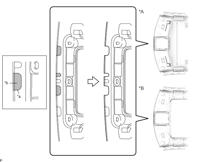
| *A | for Standard Roof | *B | for Sliding Roof |
| *a | Marking | *b | Cut |
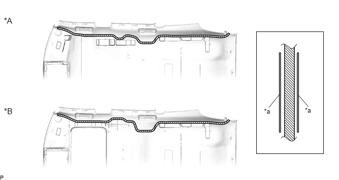
(b) Apply butyl tape as shown in the illustration.
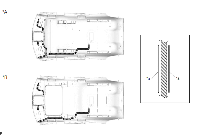
| *A | for Standard Roof | *B | for Sliding Roof |
| *a | Marking | - | - |
.png) | Butyl Tape | - | - |
NOTICE:
Securely attach the butyl tape.
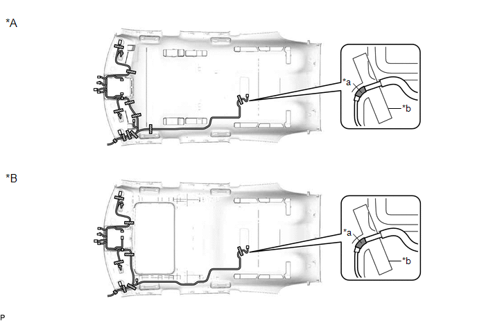
(c) Turn the 2 visor connectors clockwise approximately 90° to install them to the roof headlining assembly.
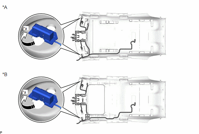
| *A | for Standard Roof | *B | for Sliding Roof |
| *a | 90° | - | - |
.png) | Rotation Direction | - | - |
(d) Engage each clamp.
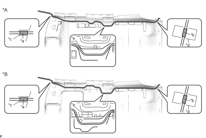
(e) Align the marking tape (A) on the No. 1 roof wire with the vehicle front side tab of the roof headlining assembly.
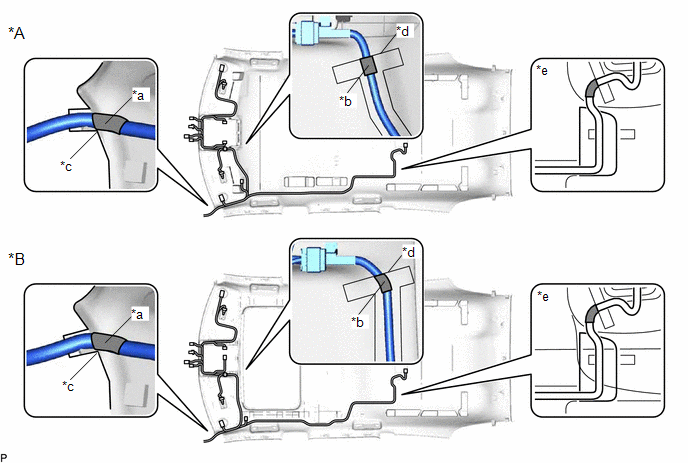
| *A | for Standard Roof | *B | for Sliding Roof |
| *a | Marking Tape (A) | *b | Marking Tape (B) |
| *c | Vehicle Front Side Tab of the Roof Headlining Assembly | *d | Marking |
| *e | Adjustment Area | - | - |
(f) Align the edge of the marking tape (B) on the No. 1 roof wire with the markings on the roof headlining assembly.
(g) Attach the No. 1 roof wire with the butyl tape.
NOTICE:
- Securely attach the No. 1 roof wire.
- If any of the No. 1 roof wire is left loose, it will cause an abnormal noise.
- Make sure to attach the No. 1 roof wire without leaving any of it loose.
HINT:
Secure the extra length of the No. 1 roof wire in the adjustment area.
(h) Align the edge of the marking tape (C) on the No. 1 roof wire with the markings on the roof headlining assembly.
| *A | for Standard Roof | *B | for Sliding Roof |
| *a | Marking Tape (C) | *b | Marking |
| | Adhesive Tape | - | - |
(i) Install the No. 1 roof wire to the roof headlining assembly with adhesive tape.
NOTICE:
- Apply the tape securely in place.
- Do not touch the adhesive surface when applying the tape to prevent adhesion failure.
2. INSTALL TELEPHONE MICROPHONE ASSEMBLY
Click here .gif)
3. INSTALL VANITY LIGHT ASSEMBLY
Click here
4. INSTALL WASHER HOSE ASSEMBLY
(a) Apply butyl tape as shown in the illustration.
| *A | for Standard Roof | *B | for Sliding Roof |
| *a | Marking | - | - |
| | Butyl Tape | - | - |
NOTICE:
Securely attach the butyl tape.
(b) Align the marking tape (A) on the washer hose assembly with the vehicle front side tab of the roof headlining assembly.
| *A | for Standard Roof | *B | for Sliding Roof |
| *a | Marking Tape (A) | *b | Marking Tape (B) |
| *c | Vehicle Front Side Tab of the Roof Headlining Assembly | *d | Marking |
| *e | Adjustment Area | - | - |
(c) Align the edge of the marking tape (B) on the washer hose assembly with the marking on the roof headlining assembly.
(d) Attach the washer hose assembly with the butyl tape.
NOTICE:
- Securely attach the washer hose assembly.
- If any of the washer hose assembly is left loose, it will cause an abnormal noise.
- Make sure to attach the washer hose assembly without leaving any of it loose.
HINT:
Secure the extra length of the washer hose assembly in the adjustment area.
5. INSTALL NO. 2 ANTENNA CORD SUB-ASSEMBLY
Click here
 Installation
INSTALLATION PROCEDURE 1. INSTALL ROOF HEADLINING ASSEMBLY (a) Put the roof headlining assembly into the vehicle through the back door as shown in the illustration. NOTICE: Do not damage the roof head ...
 Removal
REMOVAL CAUTION / NOTICE / HINT The necessary procedures (adjustment, calibration, initialization or registration) that must be performed after parts are removed and installed, or replaced during roof ...
Other materials:
Lexus RX (RX 350L, RX450h) 2016-2026 Repair Manual > Front Axle Hub: On-vehicle Inspection
ON-VEHICLE INSPECTION CAUTION / NOTICE / HINT HINT:
Use the same procedure for the RH side and LH side.
The following procedure is for the LH side.
PROCEDURE 1. REMOVE FRONT WHEEL Click here 2. SEPARATE FRONT DISC BRAKE CALIPER ASSEMBLY Click here 3. REMOVE FRONT DISC Click here 4. INS ...
Lexus RX (RX 350L, RX450h) 2016-2026 Repair Manual > Vacuum Pump: Installation
INSTALLATION PROCEDURE 1. INSTALL VACUUM PUMP ASSEMBLY (a) When using a new vacuum pump assembly: (1) Apply engine oil to the No. 2 O-ring and No. 3 O-ring which are installed to a new vacuum pump assembly. *1 No. 2 O-ring *2 No. 3 O-ring Engine oil (b) When reusing the vacuum ...
Lexus RX (RX 350L, RX450h) 2016-{YEAR} Owners Manual
- For your information
- Pictorial index
- For safety and security
- Instrument cluster
- Operation of each component
- Driving
- Lexus Display Audio system
- Interior features
- Maintenance and care
- When trouble arises
- Vehicle specifications
- For owners
Lexus RX (RX 350L, RX450h) 2016-{YEAR} Repair Manual

0.0113