Lexus RX (RX 350L, RX450h) 2016-2026 Repair Manual: Wireless Charger Illumination Circuit
DESCRIPTION
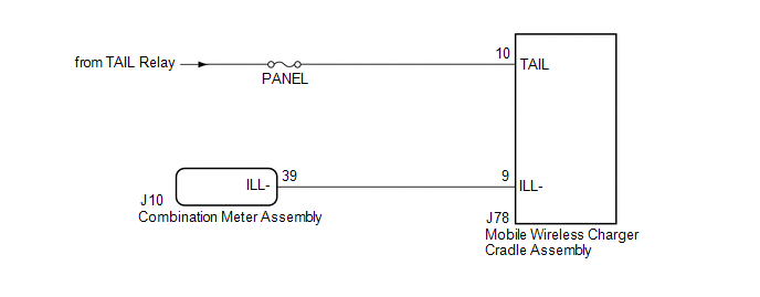
When the light control switch is turned to the tail or head position, this circuit sends an illumination signal to the mobile wireless charger cradle assembly.
WIRING DIAGRAM
CAUTION / NOTICE / HINT
NOTICE:
Inspect the fuses for circuits related to this system before performing the following procedure.
PROCEDURE
| 1. | CHECK HARNESS AND CONNECTOR (ILLUMINATION SIGNAL) |
(a) Disconnect the J78 mobile wireless charger cradle assembly connector.
(b) Measure the voltage according to the value(s) in the table below.
Standard Voltage:
| Tester Connection | Switch Condition | Specified Condition |
|---|---|---|
| J78-10 (TAIL) - Body ground | Light control switch in off position | Below 1 V |
| Light control switch in tail or head position | 11 to 14 V |
| NG | .gif) | REPAIR OR REPLACE HARNESS OR CONNECTOR |
|
.gif)
| 2. | CHECK HARNESS AND CONNECTOR (MOBILE WIRELESS CHARGER CRADLE ASSEMBLY - COMBINATION METER ASSEMBLY) |
(a) Disconnect the J10 combination meter assembly connector.
(b) Measure the resistance according to the value(s) in the table below.
Standard Resistance:
| Tester Connection | Condition | Specified Condition |
|---|---|---|
| J78-9 (ILL-) - J10-39 (ILL-) | Always | Below 1 Ω |
| J78-9 (ILL-) or J10-39 (ILL-) - Body ground | Always | 10 kΩ or higher |
| OK | | PROCEED TO NEXT SUSPECTED AREA SHOWN IN PROBLEM SYMPTOMS TABLE |
| NG | | REPAIR OR REPLACE HARNESS OR CONNECTOR |
 Status Signal Circuit
DESCRIPTION This circuit sends a charging suspension signal from the certification ECU (smart key ECU assembly) to the mobile wireless charger cradle assembly. Based on this signal, the mobile wireles ...
 Pre-collision
...
Other materials:
Lexus RX (RX 350L, RX450h) 2016-2026 Repair Manual > Seat Belt Warning System: System Description
SYSTEM DESCRIPTION SEAT BELT WARNING SYSTEM DESCRIPTION (a) Seat belt warning light operation for driver seat belt: The seat belt warning light on the combination meter assembly illuminates, blinks or turns off in accordance with the driver seat belt state, vehicle speed, shift lever position and pa ...
Lexus RX (RX 350L, RX450h) 2016-2026 Repair Manual > Sliding Roof Housing (for Panoramic Moon Roof): Removal
REMOVAL CAUTION / NOTICE / HINT The necessary procedures (adjustment, calibration, initialization or registration) that must be performed after parts are removed and installed, or replaced during sliding roof glass sub-assembly, sliding roof housing panel, sliding roof drive gear assembly, sliding r ...
Lexus RX (RX 350L, RX450h) 2016-{YEAR} Owners Manual
- For your information
- Pictorial index
- For safety and security
- Instrument cluster
- Operation of each component
- Driving
- Lexus Display Audio system
- Interior features
- Maintenance and care
- When trouble arises
- Vehicle specifications
- For owners
Lexus RX (RX 350L, RX450h) 2016-{YEAR} Repair Manual

0.0126