Lexus RX (RX 350L, RX450h) 2016-2026 Repair Manual: Terminals Of Ecu
TERMINALS OF ECU
CHECK POSITION CONTROL ECU AND SWITCH ASSEMBLY LH

(a) Disconnect the c5 and c6 position control ECU and switch assembly LH connectors.
(b) Measure the voltage and resistance according to the value(s) in the table below.
HINT:
Measure the values on the wire harness side with the connector disconnected.
| Tester Connection | Wiring Color | Terminal Description | Condition | Specified Condition |
|---|---|---|---|---|
| c5-2 (GND) - Body ground | W-B - Body ground | Ground | Always | Below 1 Ω |
| c5-7 (+B) - c5-2 (GND) | W*1, R*2 - W-B | Battery power supply | Always | 11 to 14 V |
| c6-12 (SYSB) - c5-2 (GND) | P - W-B | System power source | Always | 11 to 14 V |
| c6-3 (IG) - c5-2 (GND) | R - W-B | Ignition power supply | Engine switch on (IG) | 11 to 14 V |
| c6-3 (IG) - c5-2 (GND) | R - W-B | Ignition power supply | Engine switch off | Below 1 V |
| c6-10 (DBCL) - Body ground | GR - Body ground | Driver seat belt buckle switch signal | Driver seat belt fastened | Below 1 Ω |
| c6-10 (DBCL) - Body ground | GR - Body ground | Driver seat belt buckle switch signal | Driver seat belt unfastened | 10 kΩ or higher |
- *1: w/o Seat VariableCushion Switch
- *2: w/ Seat VariableCushion Switch
(c) Reconnect the c5 and c6 position control ECU and switch assembly LH connectors.
(d) Measure the voltage and resistance according to the value(s) in the table below.
| Tester Connection | Wiring Color | Terminal Description | Condition | Specified Condition |
|---|---|---|---|---|
| c5-6 (+B2) - c5-2 (GND) | SB - W-B | Lumbar support adjuster power source | Always | 11 to 14 V |
| c5-1 (GND2) - Body ground | W-B - Body ground | Lumbar support adjuster ground | Always | Below 1 Ω |
| c5-3 (SLD+) - c5-2 (GND) | L - W-B | Slide motor signal (forward) | Slide switch off | Below 1 V |
| Slide switch on (Forward) | 11 to 14 V | |||
| c5-4 (SLD-) - c5-2 (GND) | GR - W-B | Slide motor signal (rearward) | Slide switch off | Below 1 V |
| Slide switch on (Rearward) | 11 to 14 V | |||
| c5-5 (FRV-) - c5-2 (GND) | R - W-B | Front vertical motor signal (downward) | Front vertical switch off | Below 1 V |
| Front vertical switch on (Downward) | 11 to 14 V | |||
| c5-8 (FRV+) - c5-2 (GND) | B - W-B | Front vertical motor signal (upward) | Front vertical switch off | Below 1 V |
| Front vertical switch on (Upward) | 11 to 14 V | |||
| c5-9 (RCL+) - c5-2 (GND) | P - W-B | Reclining motor signal (forward) | Reclining switch off | Below 1 V |
| Reclining switch on (Forward) | 11 to 14 V | |||
| c5-11 (RCL-) - c5-2 (GND) | LG - W-B | Reclining motor signal (rearward) | Reclining switch off | Below 1 V |
| Reclining switch on (Rearward) | 11 to 14 V | |||
| c5-10 (LFT+) - c5-2 (GND) | V - W-B | Lifter motor signal (upward) | Lifter switch off | Below 1 V |
| Lifter switch on (Upward) | 11 to 14 V | |||
| c5-12 (LFT-) - c5-2 (GND) | G - W-B | Lifter motor signal (downward) | Lifter switch off | Below 1 V |
| Lifter switch on (Downward) | 11 to 14 V | |||
| c6-1 (SGND) - c5-2 (GND) | BR - W-B | Position sensor ground | Always | Below 1 Ω |
| c6-5 (SSRS) - c6-1 (SGND) | G- BR | Slide position signal | Slide function operating | 4.8 to 5.1 V |
CHECK OUTER MIRROR CONTROL ECU ASSEMBLY (DRIVER DOOR)
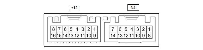
(a) Disconnect the N4 outer mirror control ECU assembly (driver door) connector.
(b) Measure the voltage and resistance according to the value(s) in the table below.
HINT:
Measure the values on the wire harness side with the connector disconnected.
| Tester Connection | Wiring Color | Terminal Description | Condition | Specified Condition |
|---|---|---|---|---|
| N4-6 (CPUB) - N4-7 (GND) | L - W-B | Battery power supply | Always | 11 to 14 V |
| N4-14 (BDR) - N4-7 (GND) | L - W-B | Battery power supply | Always | 11 to 14 V |
| N4-5 (SIG) - N4-7 (GND) | Y - W-B | Ignition power supply | Engine switch on (IG) | 11 to 14 V |
| N4-5 (SIG) - N4-7 (GND) | Y - W-B | Ignition power supply | Always | Below 1 V |
| N4-7 (GND) - Body ground | W-B - Body ground | Ground | Always | Below 1 Ω |
(c) Reconnect the N4 outer mirror control ECU assembly (driver door) connector.
(d) Measure the voltage according to the value(s) in the table below.
| Tester Connection | Wiring Color | Terminal Description | Condition | Specified Condition |
|---|---|---|---|---|
| N4-1 (MM) - N4-7 (GND) | W - W-B | SET switch signal for seat memory switch LH | SET switch on | Below 1 V |
| SET switch off | 11 to 14 V | |||
| N4-2 (M1) - N4-7 (GND) | G - W-B | M1 switch signal for seat memory switch LH | M1 switch on | Below 1 V |
| M1 switch off | 11 to 14 V | |||
| N4-3 (M2) - N4-7 (GND) | V - W-B | M2 switch signal for seat memory switch LH | M2 switch on | Below 1 V |
| M2 switch off | 11 to 14 V | |||
| N4-4 (M3) - N4-7 (GND) | R - W-B | M3 switch signal for seat memory switch LH | M3 switch on | Below 1 V |
| M3 switch off | 11 to 14 V |
CHECK MAIN BODY ECU (MULTIPLEX NETWORK BODY ECU) AND INSTRUMENT PANEL JUNCTION BLOCK ASSEMBLY
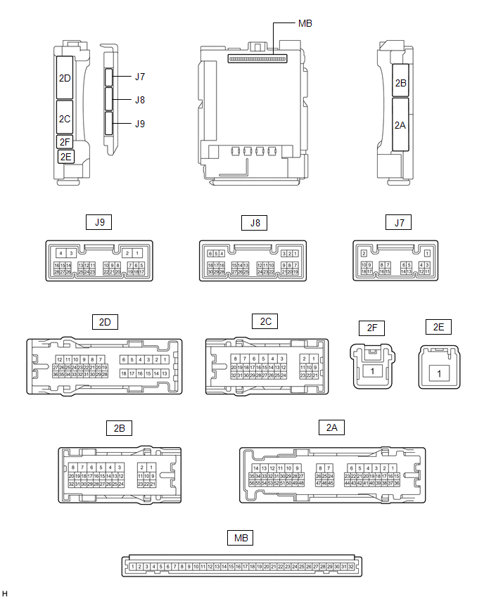
(a) Remove the main body ECU (multiplex network body ECU) from the instrument panel junction block assembly.
Click here .gif)
(b) Measure the voltage and resistance according to the value(s) in the table below.
HINT:
Measure the values on the wire harness side with the connector disconnected.
| Tester Connection | Wiring Color | Terminal Description | Condition | Specified Condition |
|---|---|---|---|---|
| MB-31 (BECU) - Body ground | - | Battery power supply | Always | 11 to 14 V |
| MB-32 (IG) - Body ground | - | Ignition power supply | Engine switch on (IG) | 11 to 14 V |
| MB-32 (IG) - Body ground | - | Ignition power supply | Engine switch off | Below 1 V |
| MB-30 (ACC) - Body ground | - | Ignition power supply | Engine switch on (ACC) | 11 to 14 V |
| MB-30 (ACC) - Body ground | - | Ignition power supply | Engine switch off | Below 1 V |
| MB-11 (GND1) - Body ground | - | Ground | Always | Below 1 Ω |
| J8-6 (FLCY) - Body ground | P - Body ground | Front door courtesy light switch assembly (driver door) input | Front door LH closed (OFF) → open (ON) | 10 kΩ or higher → Below 1 Ω |
If the result is not as specified, there may be a malfunction in the wire harness.
 Problem Symptoms Table
PROBLEM SYMPTOMS TABLE HINT:
Use the table below to help determine the cause of problem symptoms. If multiple suspected areas are listed, the potential causes of the symptoms are listed in order of ...
 Diagnosis System
DIAGNOSIS SYSTEM DESCRIPTION (a) Front power seat control system (w/ Memory) data and Diagnostic Trouble Codes (DTCs) can be read through the Data Link Connector 3 (DLC3) of the vehicle. When the syst ...
Other materials:
Lexus RX (RX 350L, RX450h) 2016-2026 Owners Manual > Child restraint systems: Using an anchor bracket (for top tether strap)
■ Anchor brackets (for top tether strap)
Anchor brackets are provided for the following seats:
Second-row seats (RX450h)
Second-row seats (RX450hL)
Third-row left side seat
■ Fixing the top tether strap to the anchor bracket (second-row seats)
Install the child restraint system in ac ...
Lexus RX (RX 350L, RX450h) 2016-2026 Repair Manual > Vehicle Stability Control System: Stop Lamp Relay Actuator Stuck On (C13807E)
DESCRIPTION When any of the following conditions are met, the skid control ECU (brake actuator assembly) sets the drive output (STPO) ON which operates the stop light control relay (stop light switch assembly) and turns on the stop lights. Illumination Conditions:
Pre-collision brake is operating ...
Lexus RX (RX 350L, RX450h) 2016-{YEAR} Owners Manual
- For your information
- Pictorial index
- For safety and security
- Instrument cluster
- Operation of each component
- Driving
- Lexus Display Audio system
- Interior features
- Maintenance and care
- When trouble arises
- Vehicle specifications
- For owners
Lexus RX (RX 350L, RX450h) 2016-{YEAR} Repair Manual

0.009