Lexus RX (RX 350L, RX450h) 2016-2026 Repair Manual: Inspection
INSPECTION
PROCEDURE
1. INSPECT NO. 2 SEAT CUSHION FRAME SUB-ASSEMBLY RH
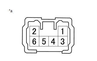
| *a | Component without harness connected (No. 2 Seat Cushion Frame Sub-assembly RH) |
(a) Apply battery voltage to the lifter motor connector, and check that the No.2 seat cushion frame sub-assembly RH operates smoothly as follows.
OK:
| Battery Connection | Specified Condition |
|---|---|
| Battery positive (+) → Terminal 4 Battery negative (-) → Terminal 3 | Downward |
| Battery positive (+) → Terminal 3 Battery negative (-) → Terminal 4 | Upward |
2. INSPECT NO. 2 SEATBACK FRAME SUB-ASSEMBLY RH
| *a | Component without harness connected (No. 2 Seatback Frame Sub-assembly RH) |
(a) Apply battery voltage to the reclining motor connector, and check that the No.2 seatback frame sub-assembly RH operates smoothly as follows.
OK:
| Battery Connection | Specified Condition |
|---|---|
| Battery positive (+) → Terminal 3 Battery negative (-) → Terminal 4 | Forward |
| Battery positive (+) → Terminal 4 Battery negative (-) → Terminal 3 | Backward |
3. INSPECT NO. 2 SEAT CUSHION FRAME SUB-ASSEMBLY LH
| *a | Component without harness connected (No. 2 Seat Cushion Frame Sub-assembly LH) |
(a) Apply battery voltage to the lifter motor connector, and check that the No.2 seat cushion frame sub-assembly LH operates smoothly as follows.
OK:
| Battery Connection | Specified Condition |
|---|---|
| Battery positive (+) → Terminal 4 Battery negative (-) → Terminal 3 | Downward |
| Battery positive (+) → Terminal 3 Battery negative (-) → Terminal 4 | Upward |
4. INSPECT NO. 2 SEATBACK FRAME SUB-ASSEMBLY LH
| *a | Component without harness connected (No. 2 Seatback Frame Sub-assembly LH) |
(a) Apply battery voltage to the reclining motor connector, and check that the No.2 seatback frame sub-assembly LH operates smoothly as follows.
OK:
| Battery Connection | Specified Condition |
|---|---|
| Battery positive (+) → Terminal 3 Battery negative (-) → Terminal 4 | Forward |
| Battery positive (+) → Terminal 4 Battery negative (-) → Terminal 3 | Backward |
 Components
COMPONENTS ILLUSTRATION *1 DECK BOARD ASSEMBLY *2 NO. 1 DECK BOARD *3 REAR NO. 4 FLOOR BOARD *4 TONNEAU COVER ASSEMBLY ILLUSTRATION *A w/o Woofer *B w/ Woofer *1 ...
 Installation
INSTALLATION CAUTION / NOTICE / HINT CAUTION: Wear protective gloves. Sharp areas on the seat frame may injure your hands. PROCEDURE 1. INSTALL REAR NO. 2 SEAT ASSEMBLY (a) Place the rear No. 2 seat a ...
Other materials:
Lexus RX (RX 350L, RX450h) 2016-2026 Repair Manual > Vehicle Stability Control System: Brake Switch "A" Circuit Open (P057113)
DESCRIPTION The skid control ECU (brake actuator assembly) detects the brake operating conditions through a signal transmitted by the stop light switch. The skid control ECU incorporates a circuit to detect an open circuit. This DTC is output when an open circuit is detected in the stop light signal ...
Lexus RX (RX 350L, RX450h) 2016-2026 Repair Manual > Sfi System: Engine Coolant Temperature Sensor 1 Circuit Short to Battery or Open (P011515)
DESCRIPTION Refer to DTC P011511. Click here HINT: When DTC P011515 is stored, the ECM enters fail-safe mode. During fail-safe mode, the engine coolant temperature is estimated to be 80°C (176°F) by the ECM. Fail-safe mode continues until a pass condition is detected. DTC No. Detection Item ...
Lexus RX (RX 350L, RX450h) 2016-{YEAR} Owners Manual
- For your information
- Pictorial index
- For safety and security
- Instrument cluster
- Operation of each component
- Driving
- Lexus Display Audio system
- Interior features
- Maintenance and care
- When trouble arises
- Vehicle specifications
- For owners
Lexus RX (RX 350L, RX450h) 2016-{YEAR} Repair Manual

0.0114